

Efficient and long-service-life hydraulic valve main hole machining method
A hole processing method and hydraulic valve technology, which are applied in metal processing equipment, workpieces, manufacturing tools, etc., can solve the problems of reducing the reaming and cutting vibration, the residual chips clogging the holes, and the poor machining accuracy, so as to improve the reaming machining allowance. And cutting efficiency, improve surface roughness and cylindricity, good effect of concentricity
- Summary
- Abstract
- Description
- Claims
- Application Information
AI Technical Summary
Problems solved by technology
Method used
Image

Examples
Embodiment
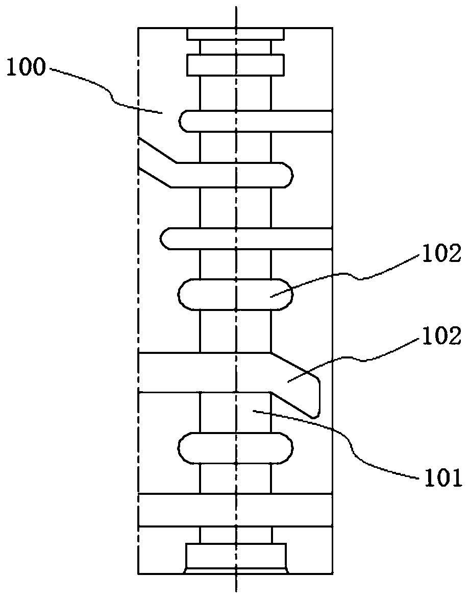
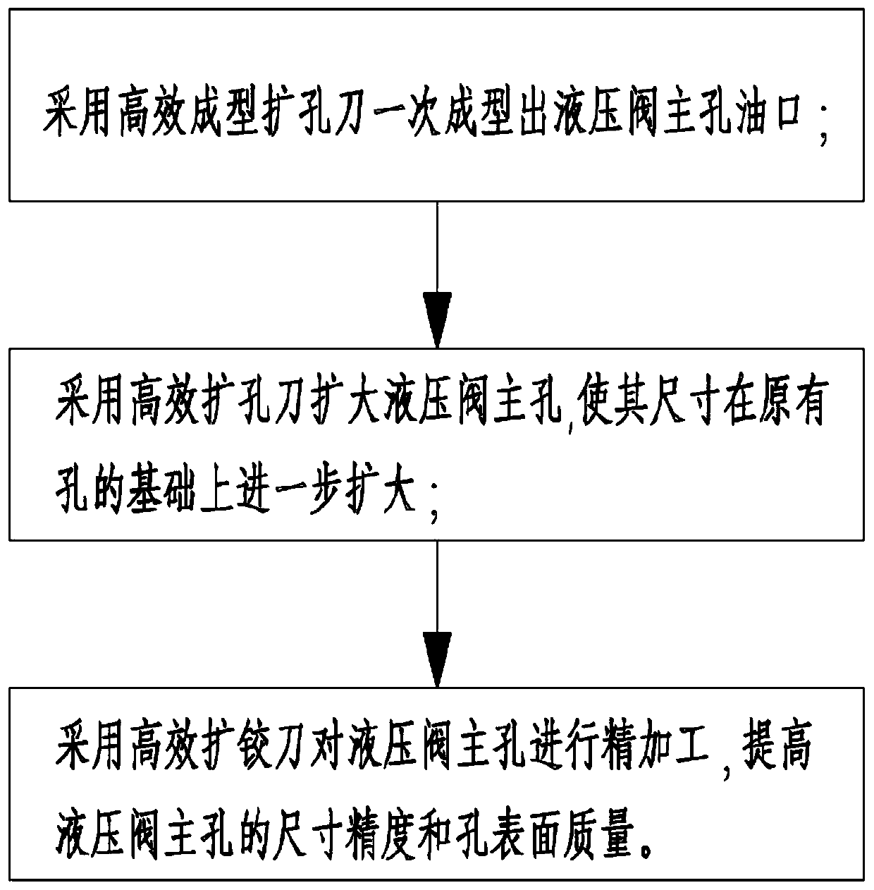
[0058] see figure 2 As shown, a high-efficiency, long-life hydraulic valve main hole processing method in this embodiment includes the following steps:
[0059] S1. Reaming the oil port of the main hole of the hydraulic valve: the oil port of the main hole of the hydraulic valve is formed by one-time reaming with a three-edged forming knife for the oil port;
[0060] S2. Reaming the main hole of the hydraulic valve: use the three-blade reaming knife 2 to ream the main hole of the hydraulic valve, so that the main hole of the hydraulic valve can further expand the aperture size on the basis of the original rough hole;
[0061] S3. Expanding and reaming the main hole of the hydraulic valve: the eight-edged reamer 3 is used to finish the main hole of the hydraulic valve to improve the dimensional accuracy and surface quality of the main hole of the hydraulic valve.
[0062] A high-efficiency and long-life hydraulic valve main hole processing method in this embodiment divides th...
PUM
 Abstract
Description
Claims
Application Information