Optical glass polishing device

A technology of optical glass and polishing device, which is applied in the direction of grinding drive device, grinding/polishing equipment, surface polishing machine tool, etc., can solve the problems of inability to polish optical glass, inconvenient fixing of optical glass, insufficient polishing, etc., and achieve improvement The effect of polishing degree, convenient fixing and convenient flipping

Inactive Publication Date: 2020-04-14
江苏欧达光学有限公司
View PDF5 Cites 10 Cited by
  • Summary
  • Abstract
  • Description
  • Claims
  • Application Information

AI Technical Summary

Problems solved by technology

[0003] The existing optical glass polishing device is inconvenient to fix the optical glass whose surface is a circular arc surface, the polishing is not sufficient, and it is inconvenient to turn over the surface, and cannot polish the two sides of the optical glass. Therefore, in view of the above current situation, it is urgent to develop an optical glass The glass is fixed conveniently, the optical glass is fully polished, and the optical glass polishing device is convenient for turning over the optical glass, so as to overcome the shortcomings in the current practical application and meet the current needs

Method used


Image

  • Optical glass polishing device
  • Optical glass polishing device

Examples


Embodiment 1

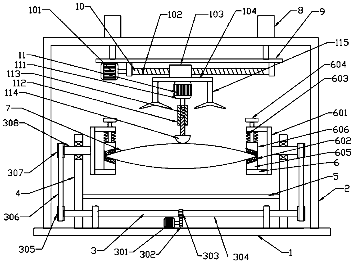
[0019] see Figure 1~2 , in an embodiment of the present invention, an optical glass polishing device includes a base 1, and a turning mechanism 3 is installed on the base 1, and the turning mechanism 3 includes: a first motor 301, a first gear 302, and a second gear 303 , the first rotating shaft 304, the driving wheel 305, the transmission belt 306, the driven wheel 307 and the second rotating shaft 308, the first rotating shaft 304 is installed on the base 1, and a driving wheel is symmetrically installed at the left and right ends of the first rotating shaft 304 305, a driven wheel 307 is respectively installed above the two driving wheels 305, the driving wheel 305 and the driven wheel 307 are rotationally connected by a transmission belt 306, and the two driven wheels 307 are respectively installed on a second rotating shaft 308 , the left and right sides of the base 1 are respectively equipped with a vertical plate 4 for installing the second rotating shaft 308, an impu...

Embodiment 2

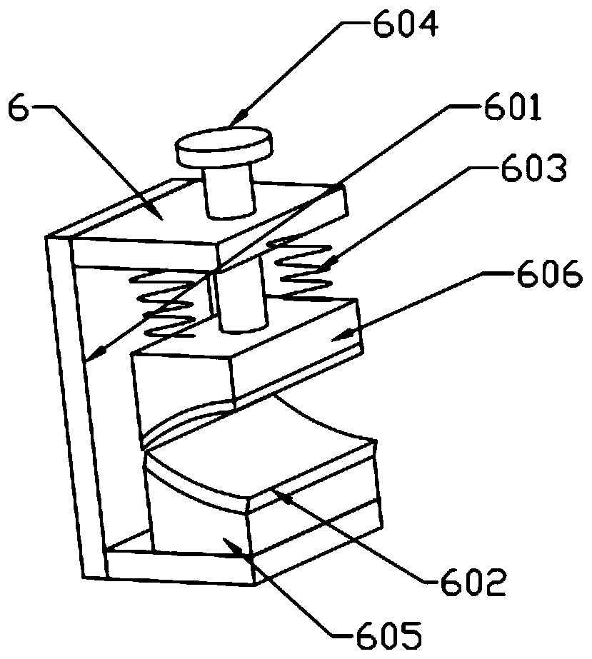
[0021] see Figure 1~2 , in the embodiment of the present invention, the clamping mechanism 6 includes: a main body frame 601, a protective cover 602, a first spring 603, a clamp 604, a lower clamping block 605 and an upper clamping block 606, the inside of the main body frame 601 A lower clamping block 605 is installed at the bottom, and an upper clamping block 606 used in conjunction with it is installed above the lower clamping block 605. The upper clamping block 606 is connected to the main body frame 601 through a plurality of first springs 603. A protective sleeve 602 is installed on the lower block 605 and the upper block 606 , and the clamp 604 for pushing the upper block 606 is installed on the main body frame 601 .

[0022] In this optical glass polishing device, the two ends of the curved optical glass 7 are respectively placed in a clamping mechanism 6, and the upper block 606 is driven to move downward by rotating the clamp 604, and the curved optical glass 7 is f...


PUM


Abstract

The invention discloses an optical glass polishing device. A base is included. A turnover mechanism is mounted on the base. Two clamping mechanisms connected with the turnover mechanism are mounted above the base. Cambered surface optical glass is installed between the two clamping mechanisms, a support is installed above the cambered surface optical glass and is installed on the base, electric cylinders are symmetrically installed at a left end and a right end of the top of the support, telescopic rods of the electric cylinders are connected with a lifting plate, a transverse moving mechanismis installed on the lifting plate, and a polishing mechanism is installed on the transverse moving mechanism. The optical glass polishing device is convenient to fix optical glass, is sufficient in polishing of the optical glass and is convenient to turn over the optical glass.

Description

technical field [0001] The invention relates to the technical field of optical glass, in particular to an optical glass polishing device. Background technique [0002] Optical glass is a glass that can change the direction of light propagation and change the relative spectral distribution of ultraviolet, visible or infrared light. Optical glass in the narrow sense refers to colorless optical glass; optical glass in the broad sense also includes colored optical glass, laser glass, quartz optical glass, anti-radiation glass, ultraviolet and infrared optical glass, fiber optic glass, acousto-optic glass, magneto-optical glass and photochromic Glass. Optical glass can be used to manufacture lenses, prisms, mirrors and windows in optical instruments. Components made of optical glass are key elements in optical instruments. Glass materials used in the manufacture of lenses, prisms, mirrors, windows, etc. for optical instruments or mechanical systems. Including colorless optica...

Claims


Application Information

Patent Timeline
Patent Type & Authority Applications(China)
IPC IPC(8): B24B29/02B24B41/06B24B47/12B08B5/02
CPCB08B5/02B24B29/02B24B41/06B24B47/12
Inventor 蒋俊杰
Owner 江苏欧达光学有限公司
Why Eureka
Try Eureka