
Plasma ignition and combustion-supporting combustion chamber for combusting low-calorific-value gas fuel

A low calorific value gas, plasma ignition technology, applied in the combustion chamber, combustion ignition, continuous combustion chamber, etc., can solve the problems of increasing the complexity of the gas turbine system, failing to meet the requirements of energy saving, and exceeding the content of NOX, and achieving strong practicality. value, avoid the retrofit process, prevent the effect of excessive temperature

Active Publication Date: 2020-04-14
HARBIN ENG UNIV
View PDF10 Cites 3 Cited by
  • Summary
  • Abstract
  • Description
  • Claims
  • Application Information

AI Technical Summary

Problems solved by technology

[0004] However, there are some problems in these methods: firstly, a large amount of fuels with high calorific value such as coke oven gas and natural gas need to be consumed during stable ignition and stable combustion, which cannot meet the requirements of energy saving; The method of improvement will make the NOX content in the tail gas discharged from the combustion chamber exceed the requirements of environmental protection standards, resulting in black smoke, so that the emission reduction requirements cannot be met.
At the same time, these measures not only increase the complexity of the gas turbine system, but also greatly increase the user's investment in infrastructure construction

Method used


Image

  • Plasma ignition and combustion-supporting combustion chamber for combusting low-calorific-value gas fuel
  • Plasma ignition and combustion-supporting combustion chamber for combusting low-calorific-value gas fuel
  • Plasma ignition and combustion-supporting combustion chamber for combusting low-calorific-value gas fuel

Examples


Embodiment Construction

[0024] The present invention will be further described in detail below in conjunction with the accompanying drawings and specific embodiments.

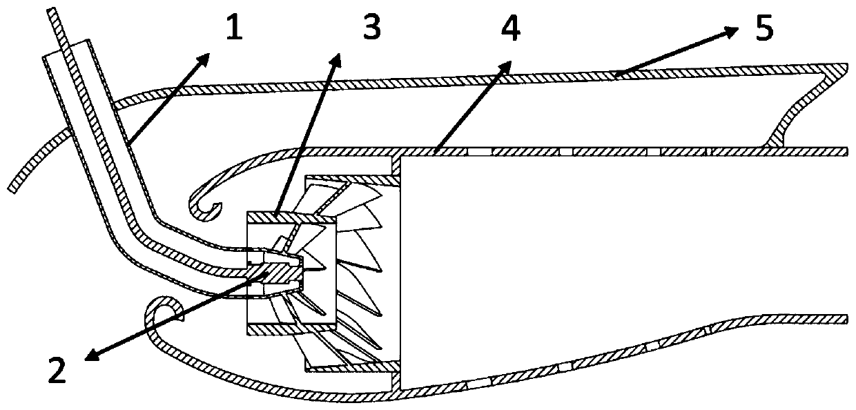
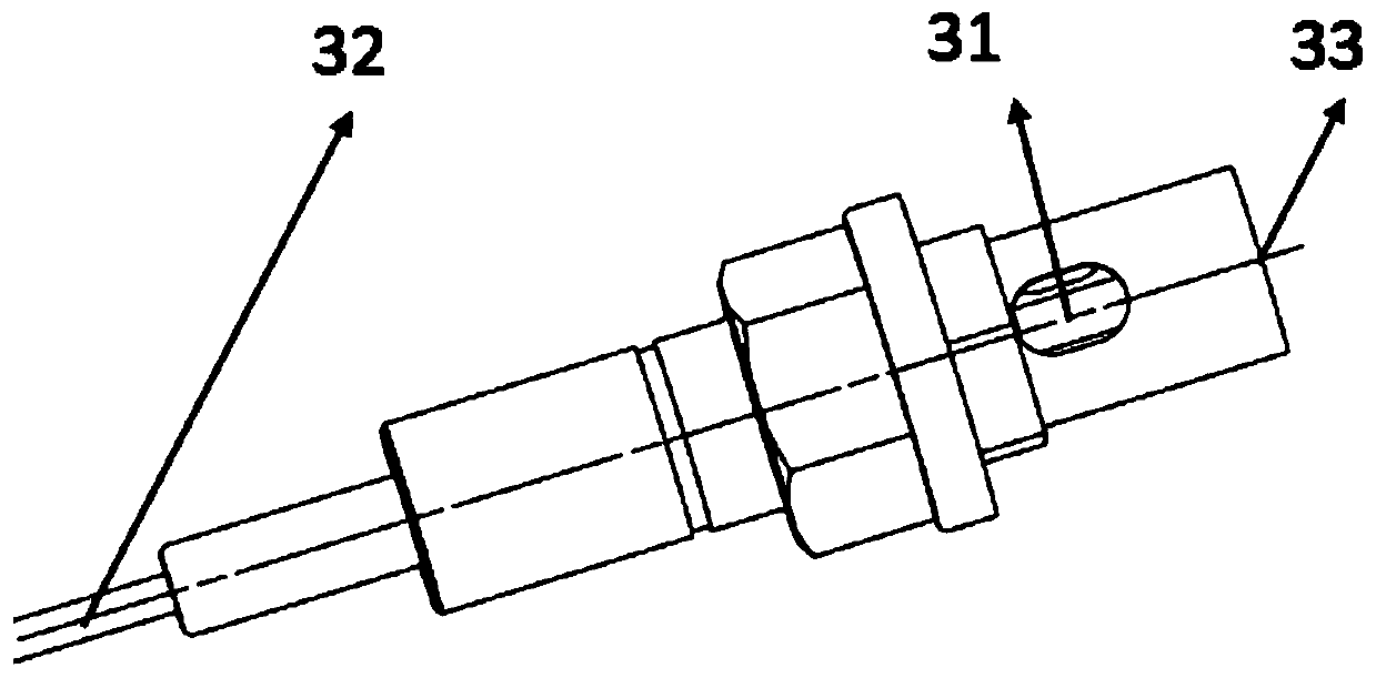
[0025] The invention relates to a plasma ignition and combustion-supporting combustion chamber for burning gas fuel with low calorific value, comprising five parts: a gas pipe, a plasma generator, a cyclone, a combustion chamber and a casing.

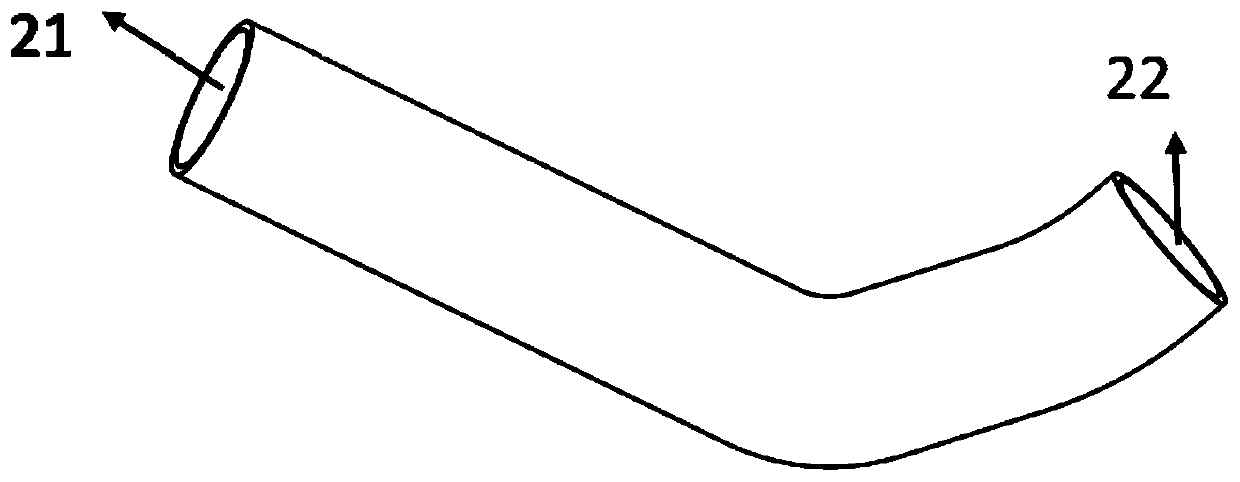
[0026] As for the gas pipe, the outlet of one end of the gas pipe is directly connected to the central pipeline of the cyclone, the inlet of the gas pipe at one end is fixed outside the casing, and the gas fuel with low calorific value can enter the central pipeline of the cyclone through the inlet of the gas pipe, and then Through the jet orifice of the central pipeline of the cyclone, it directly enters the combustion chamber for combustion, and the gas fuel with low calorific value can pass through the mixing nozzle of the central pipeline of the cyclone, and enter the primary pipeline of the...


PUM


Abstract

The invention provides a plasma ignition and combustion-supporting combustion chamber for combusting low-calorific-value gas fuel, which is characterized in that an engine brake is arranged outside the combustion chamber; a gas pipe connector is arranged at the head of the engine brake, and an air baffle connected with the combustion chamber is arranged at the tail; a swirler fixing bracket is arranged at the front part in the combustion chamber; a swirler is mounted on the swirler fixing bracket; one end of the gas pipe serves as a gas pipe inlet and is arranged on the gas pipe connector, andthe other end of the gas pipe serves as a gas pipe outlet and is connected with a central pipeline of the swirler; a plasma generator extends from an inlet of the gas pipe, and the head of the plasmagenerator is fixed to an outlet of the central pipeline of the swirler; cooling holes are formed in the outer surface of the combustion chamber; a mixing nozzle and a jet nozzle are arranged on the central pipeline of the swirler; and the jet nozzle is located at the front end of the central pipeline. The plasma generator is used for ignition and combustion supporting, and the combustion chamberof a gas turbine can be ignited more reliably and combusted more stably through active particles generated by plasmas.

Description

technical field [0001] The invention relates to a plasma ignition and combustion-supporting combustor using low-calorific-value gas fuel, in particular to a way of using plasma for ignition and combustion-supporting, so that the combustion chamber of a gas turbine can stably and reliably burn low-calorific value fuel. Background technique [0002] Low calorific value gas fuel means that the heat released by the complete combustion of 1Nm3 gas is less than 6.28MJ. Blast furnace gas is a kind of low calorific value gas fuel. Blast furnace gas is the associated gas produced in blast furnace ironmaking production. Its main components are CO, CO2, N2 and H2, etc., CO accounts for about 22% to 26%. CO2 accounts for about 16% to 19%. H2 accounts for about 1% to 4%, and N2 accounts for about 58% to 60%. The very small content of combustible gas components leads to difficulty in ignition and unstable combustion during combustion. Traditional gas turbine combustors that use high calo...

Claims


Application Information

Patent Timeline
Patent Type & Authority Applications(China)
IPC IPC(8): F23R3/26F23Q7/10
CPCF23R3/26F23Q7/10
Inventor 刘潇游滨川杨家龙孔龙陆景贺张志浩刘恩惠巩耀禛
Owner HARBIN ENG UNIV
Learn More