Experimental device for liquid metal magnetohydrodynamic generation research and using method thereof

A magnetofluidic power generation and liquid metal technology, which is used in measuring devices, measuring electricity, educational appliances, etc., can solve the problems of insufficient research investment, limited experimental parameter conditions for flexible changes, and lack of liquid metal magnetofluidic power generation channels. Research, manufacture and maintain the effect of accurate and reliable experimental basis

Pending Publication Date: 2020-04-14
SHANDONG UNIV
View PDF1 Cites 0 Cited by
  • Summary
  • Abstract
  • Description
  • Claims
  • Application Information

AI Technical Summary

Problems solved by technology

[0006] However, the inventors have found that: on the one hand, at present, there is insufficient investment in the research of liquid metal magnetic fluid power generation technology, resulting in the lack of guidance for the design of liquid metal magnetic fluid power generation channels; on the other hand, for liquid metal magnetic fluid power generation The characteristic research experiments lack systematic and standardized experimental devices and devices, and the flexible experimental parameter conditions are also limited by the experimental devices, which cannot promote the research on the theory of liquid metal magnetic fluid power generation and the characteristics of power generation channels

Method used


Image

  • Experimental device for liquid metal magnetohydrodynamic generation research and using method thereof
  • Experimental device for liquid metal magnetohydrodynamic generation research and using method thereof
  • Experimental device for liquid metal magnetohydrodynamic generation research and using method thereof

Examples


no. 1 example

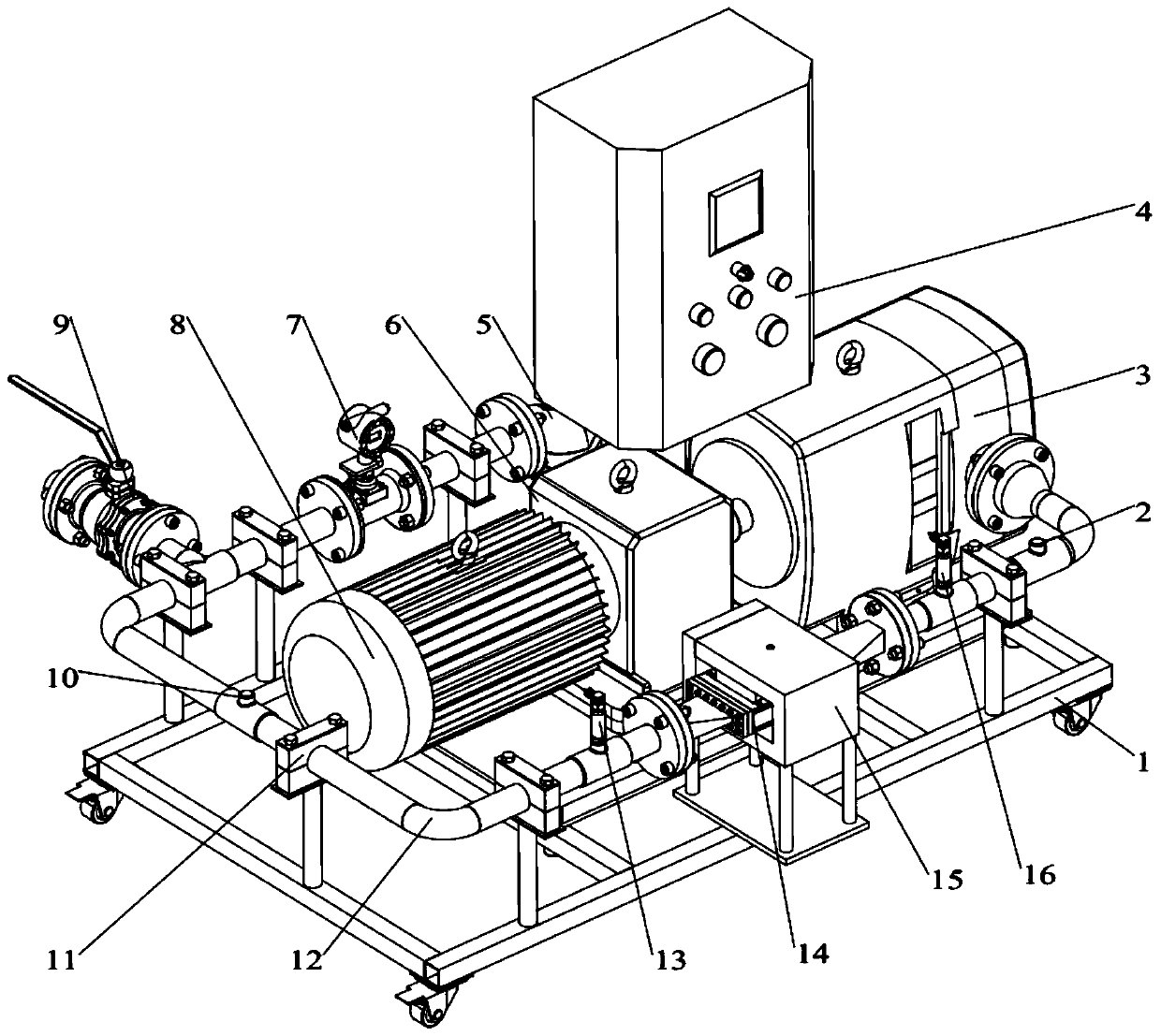
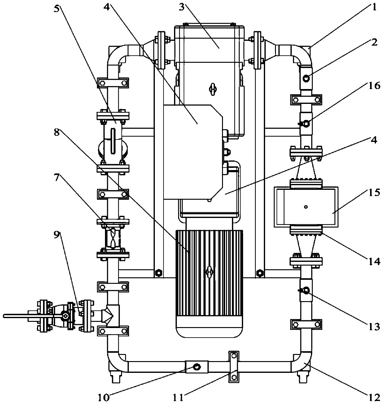
[0035] first embodiment ,refer to figure 1 and 2 , an example of an experimental device designed by the present invention for liquid metal magnetic fluid power generation research and its use method, including: pump head 3, filter 5, turbine flowmeter 7, recovery ball valve 9, pipeline 12, pre-pressure variable Transmitter 13, power generation channel 14, magnetic gathering device 15, post pressure transmitter 16.

[0036] The pipeline 12 connects the inlet of the pump head 3 of the lobe rotor pump, the filter 5, the turbine flowmeter 7, the recovery ball valve 9, the power generation channel 14 and the outlet of the pump head 3 of the rotor lobe pump through flanges to form a circulation pipe together. road.

[0037] The front pressure transmitter 13 and the rear pressure transmitter 16 are respectively installed on the pipelines at the inlet and outlet of the power generation channel 14 . The magnetic collecting device 15 surrounds the periphery of the generating channe...

no. 2 example

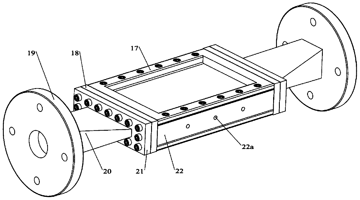
[0041] second embodiment ,refer to image 3 and 4 , the power generation channel 14 is composed of an insulating channel plate 17, an intermediate insulating flange 18, a connecting flange 19, a transition flange 21 and an electrode 22. A pair of insulating channel plates 17 and a pair of electrodes 22 are connected by screws, forming a square shape in the middle When the liquid metal magnetic fluid flows through the channel, an induced electromotive force will be generated under the action of the magnetic field. The intermediate insulating flanges 18 are divided into two groups, which are symmetrically arranged at both ends of the electrode 22 . The connecting flange 19, the reducer pipe 20 and the transition flange 21 are sealed and fixed together sequentially. The transition flange 21, the intermediate insulating flange 18, and the insulating channel plate 17 are fixed together. A wiring hole 22a is opened on the outer end surface of the electrode, which is used for con...

no. 3 example

[0043] third embodiment ,refer to Figure 5 , the magnetic gathering device 15 is a structure with a square through hole in the middle, the upper and lower opposite sides of the square through hole are respectively fixed with an N pole magnet 15c and an S pole magnet 15d, and the electrode 22 and the insulating channel plate 17 are arranged on the N pole. In the gap between the pole magnet and the S pole magnet.

[0044] The magnetic gathering device 15 of this structure can be replaced with magnets of different strengths, and the influence of different magnetic field strengths on the characteristics of the power generation channel can be studied. In addition, during installation, since the power generation channel and the magnet are a separate design, it is convenient to replace magnets of different strengths in the progress of subsequent experiments, and to study the influence of different magnetic field strengths on the characteristics of the power generation channel. The...


PUM


Abstract

The invention relates to the field of liquid metal magnetohydrodynamic generation devices, in particular to an experimental device for liquid metal magnetohydrodynamic generation research and a usingmethod thereof. The experimental device comprises a pump head, a filter, a turbine flowmeter, a recovery ball valve, a pipeline, a front pressure transmitter, a power generation channel, a magnetism gathering device and a rear pressure transmitter. An inlet of the pump head of a cam rotor pump, the filter, the turbine flowmeter, the recovery ball valve, the power generation channel and an outlet of the pump head of the cam rotor pump are connected together by the pipeline through flanges to form a circulating pipeline; the front pressure transmitter and the rear pressure transmitter are arranged on pipelines at an inlet and an outlet of the power generation channel respectively; the magnetism gathering device surrounds the periphery of the power generation channel; and a magnet in the magnetism gathering device is in clearance fit with an insulating channel plate of the power generation channel. The experimental device designed by the invention can effectively simulate the condition ofthe power generation characteristics of the liquid metal magnetofluid, and has important significance for research and analysis of the power generation channel characteristics.

Description

technical field [0001] The invention relates to the field of liquid metal magnetic fluid power generation devices, in particular to an experimental device for research on liquid metal magnetic fluid power generation and an application method thereof. Background technique [0002] The information disclosed in the Background of the Invention is only intended to increase the understanding of the general background of the invention, and is not necessarily to be taken as an acknowledgment or any form of suggestion that the information constitutes the prior art that is already known to those skilled in the art. [0003] Liquid metal magnetic fluid power generation technology refers to the technology that drives liquid metal to cut the magnetic force line through the power generation channel, and generates induced electromotive force on the electrode to output electric energy. Compared with traditional generators, liquid metal magnetic fluid power generation only needs simple compo...

Claims


Application Information

Patent Timeline
Patent Type & Authority Applications(China)
IPC IPC(8): G01R31/00G09B23/18
CPCG01R31/00G09B23/181
Inventor 王勇乔凯王启先谢玉东霍志璞
Owner SHANDONG UNIV
Why Eureka
Try Eureka