Waste glass recycling device

A recycling device and waste glass technology, which is applied in glass recycling, mechanical material recycling, recycling technology, etc., can solve the problems affecting the subsequent recycling of waste glass and the poor quality of waste glass recycling, so as to reduce clogging, facilitate feeding, The effect of improving quality

Active Publication Date: 2021-08-20
重庆华彬伟玻璃有限公司
View PDF7 Cites 0 Cited by
  • Summary
  • Abstract
  • Description
  • Claims
  • Application Information

AI Technical Summary

Problems solved by technology

[0004] However, the impurities in the waste glass are not treated in the above way, for example: the recycling of glass bottles, there are metal caps on the glass bottles, plastic sealing rings (rings under the caps), impurities such as ceramics, etc. As a result, the recycling quality of waste glass is not good, which affects the subsequent recycling of waste glass. Therefore, it is necessary to improve the waste glass recycling device

Method used


Image

  • Waste glass recycling device
  • Waste glass recycling device
  • Waste glass recycling device

Examples


Embodiment 1

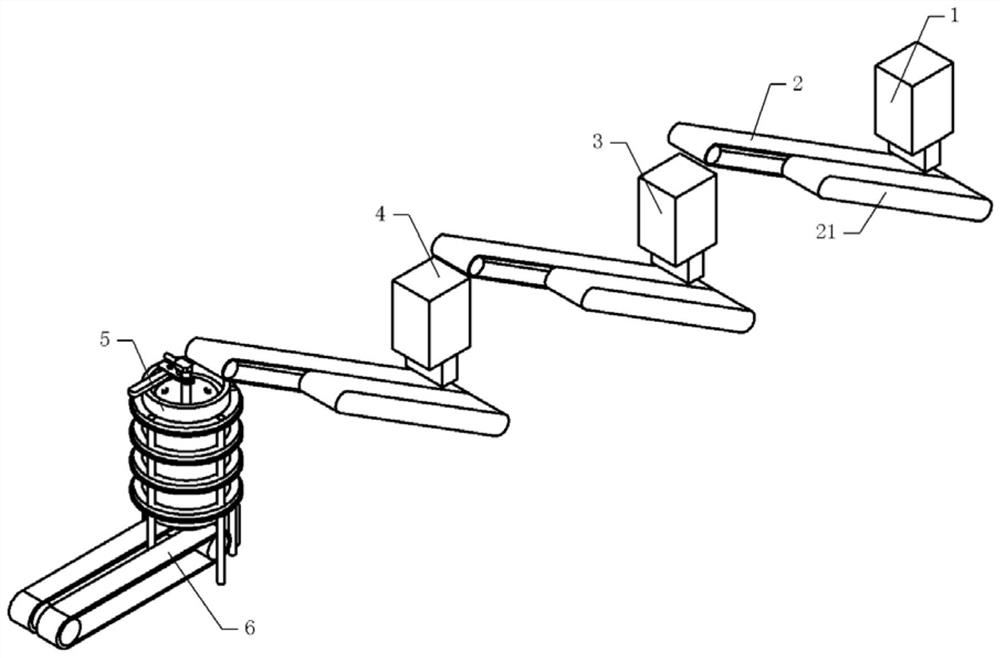
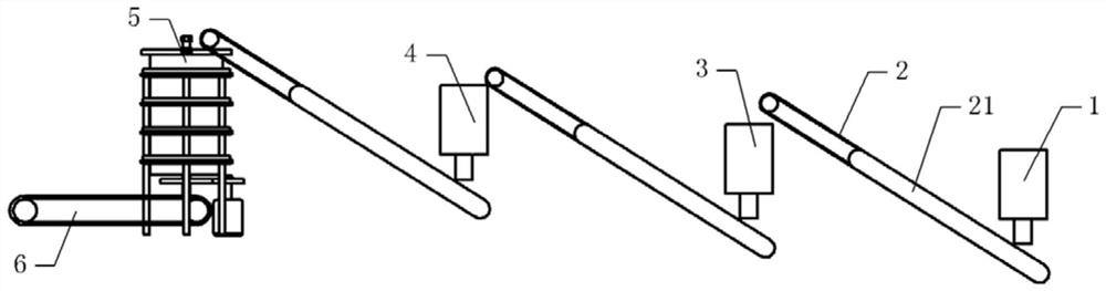
[0040] Basic as attached figure 1 And attached figure 2 As shown, a waste glass recycling device includes a frame (not shown in the figure), and the frame includes a cleaning mechanism, a magnetic separation mechanism 4, a stirring mechanism 3 and a storage box 1 from left to right, and two adjacent A conveyor belt 2 is arranged between the two mechanisms, and the conveyor belt 2 is installed on the frame, and one side of the conveyor belt 2 is provided with a workbench 21 fixed on the frame by fastening bolts.

[0041] Material storage box 1 is fixed on the frame by fastening bolt, and material storage box 1 is positioned at the top of conveyor belt 2 and broken waste glass, i.e. glass shards, is housed in the material storage box 1.

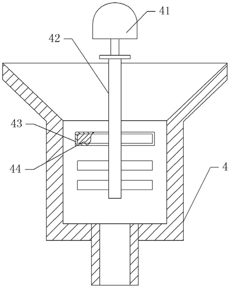
[0042] as attached image 3 As shown, the stirring mechanism 3 and the magnetic separation mechanism 4 include a stirring box fixed on the frame by fastening bolts, the top of the stirring box is provided with a tapered feed inlet in longitu...

Embodiment 2

[0055] The difference between embodiment two and embodiment one is that, as attached Figure 7 And attached Figure 8 As shown, the output shaft of the single-phase motor 54 is coaxially welded with a cam 81, and the gear 56 is horizontally slidably connected with a push plate 83 that is offset against the cam 81. A groove for sliding fit, an elastic member is arranged between the push plate 83 and the side wall of the cleaning bucket 5, the elastic piece is a spring 84 in this embodiment, and the two ends of the spring 84 are respectively welded on the side of the push plate 83 and the cleaning bucket 5 on the wall. The right side of push plate 83 is welded with cleaning shaft 82, and one side of conveyer belt 2 is provided with the blower fan that is fixed on the frame by fastening bolt.

[0056] The specific implementation process is as follows:

[0057] The single-phase motor 54 drives the cam 81 to rotate, and the cooperation of the cam 81 and the spring 84 makes the p...


PUM


Abstract

The invention relates to the technical field of glass recycling, and discloses a waste glass recycling device, which sequentially includes a cleaning mechanism, a magnetic separation mechanism, a stirring mechanism and a storage box; a conveyor belt is arranged between two adjacent mechanisms, and a conveyor belt is arranged on one side of the conveyor belt. The workbench; the magnetic separation mechanism and the stirring mechanism both include a stirring box, the upper part of the stirring box is provided with a feeding port, and a stirring shaft is rotatably connected in the stirring box, and a number of stirring blades are fixed on the stirring shaft, and a driving part is fixed on the stirring shaft. The bottom of the stirring box is provided with a discharge port; the stirring blade of the magnetic separation mechanism is fixed with an electromagnet, and the electromagnet is electrically connected with a power supply. The invention has a simple structure, can screen ceramics, metals and closed rings in the glass shards, and can remove impurities such as packaging paper adhered to the surface of the glass shards.

Description

technical field [0001] The invention relates to the technical field of glass recycling, in particular to a waste glass recycling device. Background technique [0002] Glass is a material commonly used in modern human life. It can be made into various utensils, utensils, flat glass, etc. Therefore, after the utensils are used, more waste is generated, such as glass bottles. For the sustainable utilization of resources, discarded glass and products can be collected to turn harm into benefit and waste into wealth. [0003] In the prior art, the recycling method of waste glass is to use a crusher to crush the waste glass, and then use a stirrer to stir and wash the broken glass, and then perform subsequent processing work, for example: Chinese patent, the announcement number is: CN209206012U The utility model relates to a waste glass recycling device. The waste glass is put into a pulverizer for crushing, and then put into a stirrer for stirring and cleaning, and the cleaned gl...

Claims


Application Information

Patent Timeline
Patent Type & Authority Patents(China)
IPC IPC(8): B03B9/06B03C1/22B08B3/02B07B4/00
CPCB03B9/062B03C1/22B07B4/00B08B3/022Y02W30/52Y02W30/60
Inventor 周昌伟张华平
Owner 重庆华彬伟玻璃有限公司
Why Eureka
Try Eureka