
Efficient dust removal device for solar photovoltaic panel

A technology of solar photovoltaic panels and dust removal equipment, applied in photovoltaic power generation, photovoltaic modules, electrical components, etc., can solve problems such as easy to freeze, complex cleaning channel road conditions, and unsuitable dust removal robots, etc., and achieve good contact effect

Active Publication Date: 2020-04-17
兰州瑞科新能源装备有限公司
View PDF15 Cites 5 Cited by
  • Summary
  • Abstract
  • Description
  • Claims
  • Application Information

AI Technical Summary

Problems solved by technology

The dust removal robot fixed on the photovoltaic panel is not suitable for large-scale photovoltaic power stations, and the initial investment is large, and the later maintenance is complicated; the cost of electric curtain dust removal and self-cleaning materials is too high, so they have not been well promoted; now it is common The cleaning methods of manual cleaning and car washing are adopted, the cleaning cost is high, the water demand is large, and it is easy to freeze in winter
Domestic photovoltaic power plants are mainly located in the Gobi Desert in Hexi Corridor, Qinghai, Xinjiang, Inner Mongolia and other places with rich solar energy resources, accounting for 83.7% of the country's installed photovoltaic capacity. At the same time, the installation standards of domestic photovoltaic power plants are relatively vague, the installation heights of photovoltaic panels vary greatly, and the road conditions of cleaning channels are complicated, which adds difficulty to the mechanized and efficient cleaning of photovoltaic panel dust accumulation

Method used


Image

  • Efficient dust removal device for solar photovoltaic panel
  • Efficient dust removal device for solar photovoltaic panel
  • Efficient dust removal device for solar photovoltaic panel

Examples


Embodiment Construction

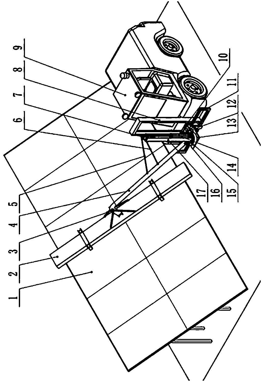
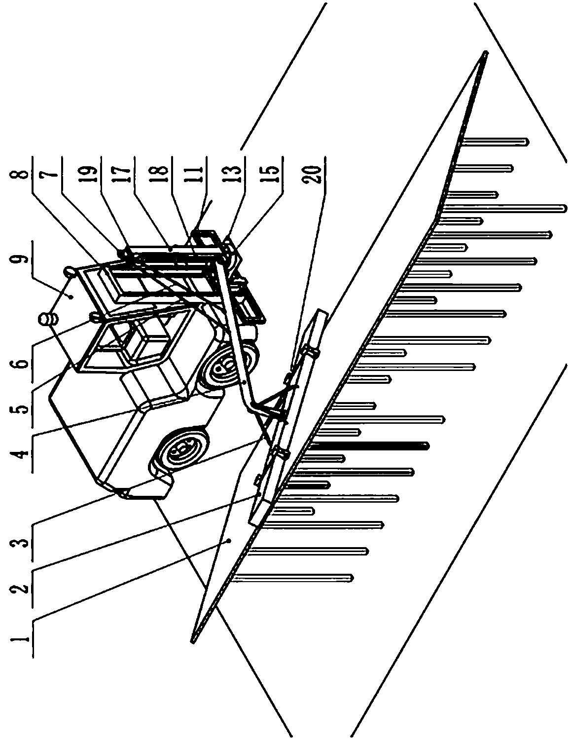
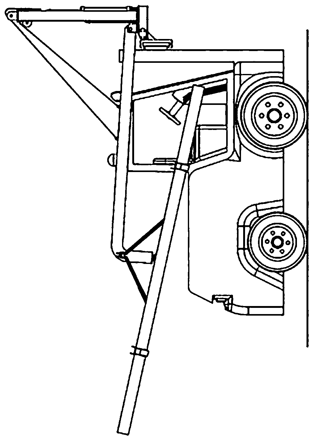
[0008] like Figure 1~Figure 4 As shown, the present invention is a high-efficiency dust removal equipment for solar photovoltaic panels, including cleaning brush 2, balance spring 3, beam 4, steel wire rope I5, steel wire rope II6, horizontal slide table 13, gas spring 14, turntable 15, hinge support 16, pull Oil cylinder 18 is lifted, and the front end of car body 9 is fixed with vertical mobile guide rail 8, and vertical slide table 10 is installed in the vertical mobile guide rail 8; Horizontal mobile guide rail 11 is fixed on the vertical slide table 10, and horizontal slide table 13 is installed on Horizontally move the guide rail 11; the turntable 15 is installed on the horizontal slide table 13, the rotating oil cylinder 12, the gas spring 14, the hinge support 16, the column 17 and the pulling cylinder 18 are installed on the turntable 15; the pulley I7 is installed on the top of the column 17, and the pulley II19 is installed on the side of the column 17 near the top...


PUM


Abstract

The invention provides an efficient dust removal device for a solar photovoltaic panel. The front end of a vehicle body 9 is fixedly provided with a vertical moving guide rail 8, and a vertical sliding table 10 is installed in the vertical moving guide rail 8; a horizontal moving guide rail 11 is fixed to the vertical sliding table 10, and a horizontal sliding table 13 is installed in the horizontal moving guide rail 11; a rotary table 15 is installed on the horizontal sliding table 13, and a rotary oil cylinder 12, a gas spring 14, a hinged support 16, an upright column 17 and a lift cylinder18 are installed on the rotary table 15. A pulley 7 is installed on the top of the upright column 17, and a pulley 19 is installed on the portion, close to the top, of the side face of the upright column 17. The root of a transverse beam 4 is fixed to the hinged support 16, one end of a steel wire rope 5 is fixed to the transverse beam 4, and the other one penetrates through the pulley 7 to be fixed to the gas spring 14; one end of a steel wire rope 6 is fixed to the transverse beam 4, and the other end penetrates through the pulley 19 to be fixed to the lift cylinder 18; a cleaning brush 2 is fixed to the transverse beam 4 through a universal hinge 20, one end of a balance spring 3 is fixed to the transverse beam 4, and the other end of the balance spring 3 is fixe to the cleaning brush.

Description

technical field [0001] The invention relates to solar photovoltaic panel dedusting equipment, and more specifically relates to a high-efficiency cleaning equipment for dust on the surface of a photovoltaic panel in a large-area solar photovoltaic power plant, which can effectively improve the power generation efficiency of the battery panel. Background technique [0002] Solar energy is one of the most reliable clean energy available to human beings at present. It has many advantages such as universality, hugeness, permanence, cheapness, greenness, and no pollution. At present, the utilization of solar energy mainly includes photothermal power generation and photovoltaic power generation. Compared with photothermal power generation, photovoltaic power generation directly converts light energy into electrical energy through the photovoltaic effect of the semiconductor interface, without other mechanical transmission and conversion devices. Therefore, the development of photov...

Claims


Application Information

Patent Timeline
Patent Type & Authority Applications(China)
IPC IPC(8): B08B1/00H02S40/10
CPCH02S40/10B08B1/30Y02E10/50
Inventor 龚俊宁会峰刘晓平张仲喜
Owner 兰州瑞科新能源装备有限公司
Learn More