Mechatronics numerical control polishing machine tool

An electromechanical and machine tool technology applied in the field of polishing machines, which can solve problems such as inability to adjust the device and incomplete dust cleaning, and achieve the effect of reducing the pressure of the telescopic rod and ensuring normal use

Inactive Publication Date: 2020-04-17
彭青珍
View PDF11 Cites 3 Cited by
  • Summary
  • Abstract
  • Description
  • Claims
  • Application Information

AI Technical Summary

Problems solved by technology

[0006] Aiming at the above-mentioned shortcomings existing in the prior art, the present invention provides an electromechanical integrated numerically controlled polishing machine tool, which can effectively overcome that the existing devices in the prior art cannot be adjusted to be suitable for polishing cylindrical workpieces of different diameters, and at the same time, polishing produces The problem of incomplete dust cleaning

Method used


Image

  • Mechatronics numerical control polishing machine tool
  • Mechatronics numerical control polishing machine tool
  • Mechatronics numerical control polishing machine tool

Examples


Embodiment 1

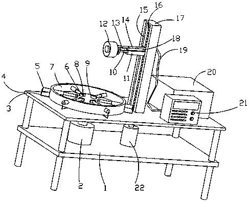
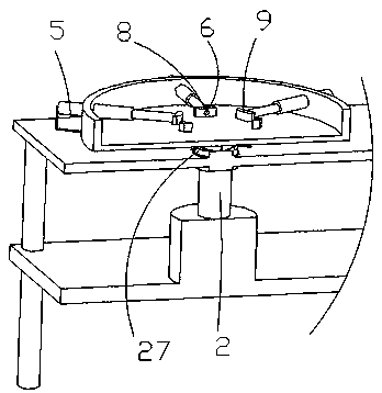
[0033] Such as figure 1 , 2 , 3 and 5, a mechatronic CNC polishing machine tool, including a base plate 1, a first rotating motor 2, a workbench 4, cables 3, a first electric push rod 5, a pressure sensor 8, a second electric push rod 10 , a vacuum cleaner 20, a controller 21, a second rotating motor 22, a polishing motor 25 and a conductive slip ring 27, the controller 21 includes a control host, a display screen and an operation keyboard, the controller 21 is electrically connected to an external power supply, and the controller 21 is respectively It is electrically connected with the first rotating motor 2, the pressure sensor 8, the second electric push rod 10, the vacuum cleaner 20, the second rotating motor 22, the polishing motor 25 and the conductive slip ring 27, and the bottom plate 1 is fixedly connected with the workbench through the support 4. The first rotating motor 2 and the second rotating motor 22 are fixedly installed on the bottom plate 1. The workbench 4 ...

Embodiment 2

[0035] Embodiment 2 is a further improvement on Embodiment 1.

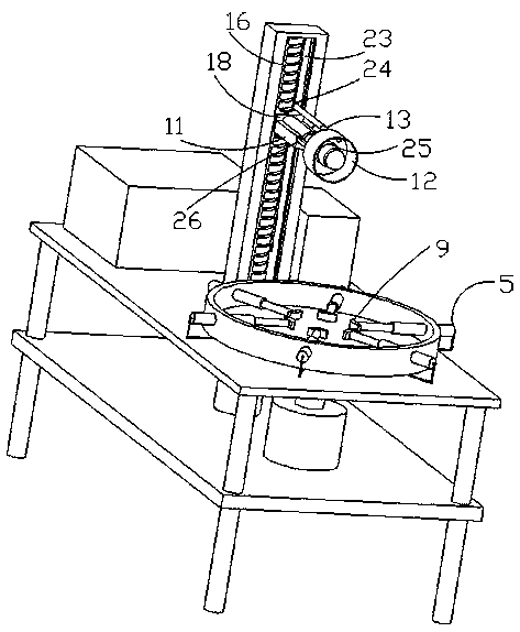
[0036] Such as figure 1 , 2 , a straight plate 17, a controller 21 and a vacuum cleaner 20 are fixedly installed on the workbench 4, a limit chute 15 is provided in the straight plate 17, and a threaded rod 16 fixedly connected with the output end of the second rotating motor 22 is provided in the limit chute 15 , the threaded rod 16 is fixedly connected with a limit slider 18, the side wall of the limit slider 18 is fixedly connected with a horizontal plate 11, and the horizontal plate 11 is fixedly installed with a second electric push rod 10 through a concave groove, and the second electric push rod The telescoping end of 10 is fixedly connected with mounting plate 28, and the side wall of mounting plate 28 is fixedly installed with polishing motor 25, and the output end of polishing motor is fixedly connected with polishing structure, cooperates by designing first electric push rod 5 and arc block 9, convenie...

Embodiment 3

[0038]Embodiment three is a further improvement on embodiment two.

[0039] Such as figure 1 , 2 4. The outer wall of the polishing motor 25 is fixedly connected with a dust collection cover 12, the dust collection cover 12 is fixedly connected with a slide tube 13, the slide tube 13 is fitted and slidably connected with a casing 14, and the limit slider 18 is attached to the limit chute 15 Sliding connection, the limit slider 18 selects dovetail block, T-shaped block or L-shaped block, the top of the limit slider 18 is fixedly connected with the installation ring 24, the sleeve 18 is fixedly installed in the installation ring 24, and the limit chute 15 The rear side wall of the rear side wall is provided with a straight hole 23 for the up and down movement of the sleeve pipe 14, the sleeve pipe 14 is fixedly connected with a hose 19, the hose 19 is fixedly connected with the input end of the vacuum cleaner 20, and the outer side of the polishing motor 25 is fixedly installed...


PUM


Abstract

The invention relates to a mechatronics numerical control polishing machine tool in the technical field of polishing machines. The mechatronics numerical control polishing machine tool comprises a bottom plate and a workbench. A first rotating motor and a second rotating motor are arranged on the bottom plate; the first rotating motor is provided with a support cylinder; the support cylinder has afirst electric push rod; the first electric push rod has an arc-shaped block; a straight plate, a controller and a dust collector are arranged on the workbench; a limiting sliding groove is formed inthe straight plate; a threaded rod is arranged in the limiting sliding groove; a limiting sliding block is arranged on the threaded rod; the limiting sliding block is provided with a transverse plate; the transverse plate is provided with a second electric push rod; the second electric push rod is provided with a mounting plate; the mounting plate is provided with a polishing motor; the polishingmotor is provided with a dust collection cover; the dust collection cover is provided with a sliding pipe; the sliding pipe is provided with a sleeve; the sleeve is provided with a hose; and the hoseis connected with a dust collector. The mechatronics numerical control polishing machine tool is convenient to adjust so as to polish cylindrical workpieces with different diameters.

Description

technical field [0001] The invention relates to the technical field of polishing machines, in particular to an electromechanical integrated numerical control polishing machine tool. Background technique [0002] Polishing refers to the use of mechanical, chemical or electrochemical action to reduce the surface roughness of the workpiece to obtain a bright and smooth surface. It is a modification process on the surface of the workpiece by using polishing tools and abrasive particles or other polishing media. The purpose of polishing is to remove the uneven layer and crack layer after fine grinding, so that the surface is transparent and smooth. [0003] Now, some numerical control polishing devices are designed for polishing cylindrical workpieces, but there are still some defects in the numerical control polishing devices. [0004] For example, Chinese patent application number CN201721640366.0 is a CNC polishing device for cylindrical workpieces, including: the frame is s...

Claims


Application Information

Patent Timeline
IPC IPC(8): B24B29/04B24B55/06B24B41/06B24B47/04B24B49/16B24B41/02B24B47/12B24B55/00
CPCB24B29/04B24B41/02B24B41/067B24B47/04B24B47/12B24B49/16B24B55/00B24B55/06
Inventor 彭青珍
Owner 彭青珍
Why Eureka
Try Eureka