Bottle blowing machine with limiting assembly

A limit component and blow molding machine technology, applied in the field of plastic processing, can solve the problems of raw material cost and transportation cost increase, large installation space, opening and closing mold structure reservation, etc., to reduce raw material cost and transportation cost, simplify assembly The difficulty of maintenance and the effect of reducing maintenance costs

Pending Publication Date: 2020-04-17
ZHEJIANG HONGZHEN MASCH MOULD GRP CO LTD
View PDF0 Cites 1 Cited by
  • Summary
  • Abstract
  • Description
  • Claims
  • Application Information

AI Technical Summary

Problems solved by technology

[0004] The existing mold opening and closing structure has the following defects: the inner end of the limit rod is fixedly connected to the back surface of the template, and when the mold assembly is switched to the mold opening station, the outer end of the limit rod will axially cross the To position the plate and move outward, it is necessary to reserve a large axial movable distance for the opening and closing mold structure;
[0009] To sum up, the existing opening and closing mold structure itself has a large axial dimension and requires a large installation space, which will not only increase the cost of raw materials and transportation due to the increase in raw material consumption, but also increase the cost due to the complexity of the structure and the weight of the parts. Larger size increases the difficulty of assembly and maintenance, and has higher requirements for installation space, which limits the installation and use of the device in workshops with small spaces and affects the applicability of the equipment

Method used


Image

  • Bottle blowing machine with limiting assembly
  • Bottle blowing machine with limiting assembly
  • Bottle blowing machine with limiting assembly

Examples


Embodiment 1

[0033] This embodiment provides a bottle blowing machine with a limit assembly.

[0034] like figure 1 The bottle blowing machine shown is composed of a frame 1 and a conveying mechanism, a heating mechanism, and a bottle blowing mechanism arranged on the frame 1. The bottle blowing mechanism includes a mold opening and closing structure and a blowing structure, and the mold opening and closing The structure includes a limiting working surface 2 with two axes parallel to each other, and a limiting component 3 and a mold component 4 separated along the axial direction are interposed between the limiting working surfaces 2, and the mold component 4 is formed by opening the mold When the station is axially closed to the mold clamping station, the limit assembly 3 moves from the idle station that is misaligned with the axial projection of the mold assembly 4 to the clamping station that coincides with the axial direction of the mold assembly 4, so that the limit working surface 2...

Embodiment 2

[0041] Compared with the first embodiment, this embodiment provides a specific blow molding machine structure.

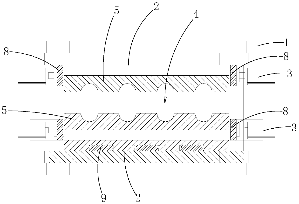
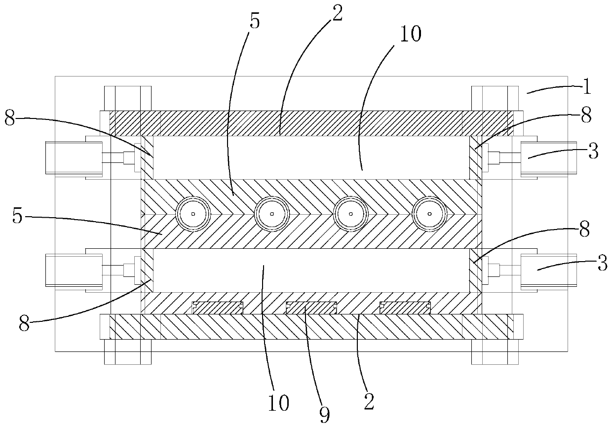
[0042] like figure 2 As shown, the mold assembly 4 includes two mold plates 5 that are arranged in parallel and can be opened and closed in the axial direction. An active space 10 for the axial displacement of the die plate 5 is formed between the limit working surfaces 2 . The film grooves are provided on the facing surfaces of the mold plates 5, so that the mold plates 5 can form a mold cavity for blowing the bottle body by facing each other. When in use, when the limit assembly 3 is switched from the clamping position to the idle position, an active space 10 is formed on the back of the mold plate 5 for its axial movement and opening, and no structure is arranged in the active space 10 , to ensure that the mold plates 5 move axially smoothly, so that the mold plates 5 move back to each other and ensure that the mold assembly 4 is switched to the mold opening s...

Embodiment 3

[0062] Compared with the second embodiment, this embodiment provides another specific blow molding machine structure.

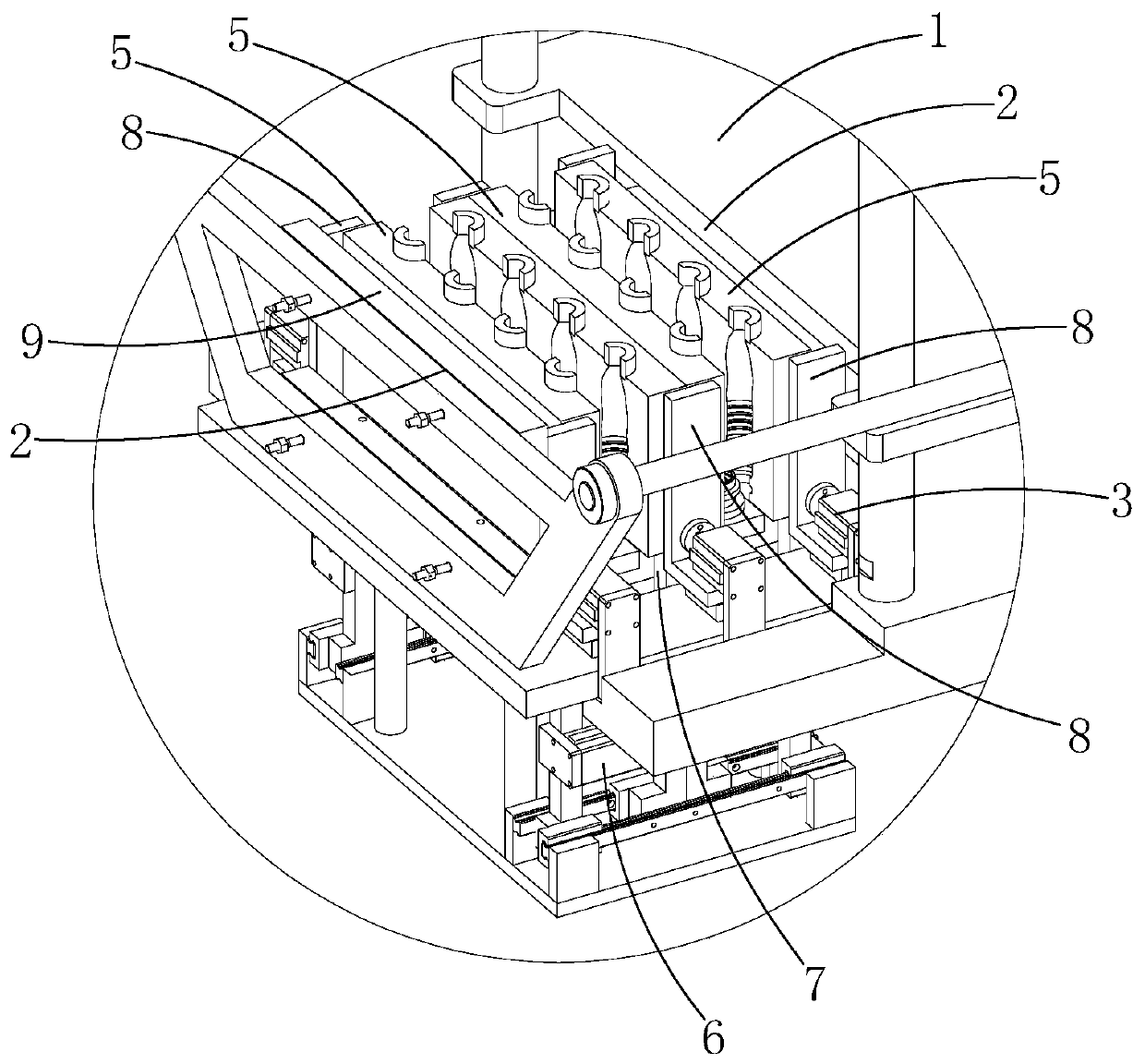
[0063] like image 3 and 4 As shown, the mold components 4 are at least two groups and are arranged at an axial distance, and a limit component 3 is provided between adjacent mold components 4, so that the limit working surface 2 axially clamps each mold component through the limit component 3 4. Specifically, the number of mold cavities is increased by increasing the number of mold components 4 between the limiting working surfaces 2, thereby increasing the number of single-mold closing and blowing bottles, effectively improving processing efficiency.

[0064] In this embodiment, when the number of mold components 4 increases, the number of said limiting components 3 will also increase accordingly, so as to ensure that each mold plate 5 has a corresponding movable space 10 . The limiting components 3 are at least two groups, and are arranged separately on...


PUM


Abstract

The invention relates to a bottle blowing machine with a limiting assembly. A mold opening and closing structure of an existing bottle blowing machine needs a large axial placement space, and use is affected. The bottle blowing machine comprises a rack, wherein the mold opening and closing structure is arranged on the rack and comprises two limiting working faces, and the limiting assembly and a mold assembly are arranged between the limiting working faces. When the mold assembly is axially closed to a mold closing station from a mold opening station, the limiting assembly moves to a clampingstation from an idle station, so that the limiting working faces axially clamp the mold assembly through the limiting assembly. The limiting assembly capable of avoiding opening and closing of the mold assembly is arranged between the limiting working faces, the limiting assembly can form a movable space through receding and can also axially clamp the mold assembly, the applicability is improved,mounting in a small placement space is facilitated, the assembly and maintenance difficulty is lowered, the maintenance cost is reduced, the raw material consumption is reduced, and the raw material cost and the transportation cost are reduced.

Description

technical field [0001] The invention relates to the field of plastic processing, in particular to a bottle blowing machine. Background technique [0002] The existing bottle blowing machine includes a frame, a conveying mechanism arranged on the frame, a heating mechanism and a bottle blowing mechanism arranged in sequence along the conveying mechanism, and the bottle blowing mechanism includes a mold opening and closing structure and a blowing structure for blowing bottles. . During operation, the preform is driven by the conveying mechanism and processed by the heating mechanism and the blowing mechanism in sequence. The heating mechanism plays a role in heating and softening the preform, and the blowing structure blows the preform. The blown preform acts as a shaper to shape the preform into a preset contour. [0003] The existing mold opening and closing structure includes two parallel and separate positioning plates, a mold assembly arranged between the positioning pl...

Claims


Application Information

Patent Timeline
Patent Type & Authority Applications(China)
IPC IPC(8): B29C49/56B29C49/48B29L22/00
CPCB29C49/48B29C49/56B29C2049/563B29C2049/566B29L2022/00
Inventor 蔡桂森蔡业
Owner ZHEJIANG HONGZHEN MASCH MOULD GRP CO LTD
Why Eureka
Try Eureka