
A multi-cathode sliding arc plasma igniter

A plasma and igniter technology, which is used in machines/engines, jet propulsion devices, gas turbine devices, etc., to achieve the effect of improving energy utilization, increasing contact area, and improving ignition ability

Active Publication Date: 2021-12-10
AIR FORCE UNIV PLA
View PDF10 Cites 0 Cited by
  • Summary
  • Abstract
  • Description
  • Claims
  • Application Information

AI Technical Summary

Problems solved by technology

However, the currently designed sliding arc plasma igniters are all single-arc structures, and only one sliding arc acts on the gas mixing area at a time.

Method used


Image

  • A multi-cathode sliding arc plasma igniter
  • A multi-cathode sliding arc plasma igniter

Examples


specific Embodiment

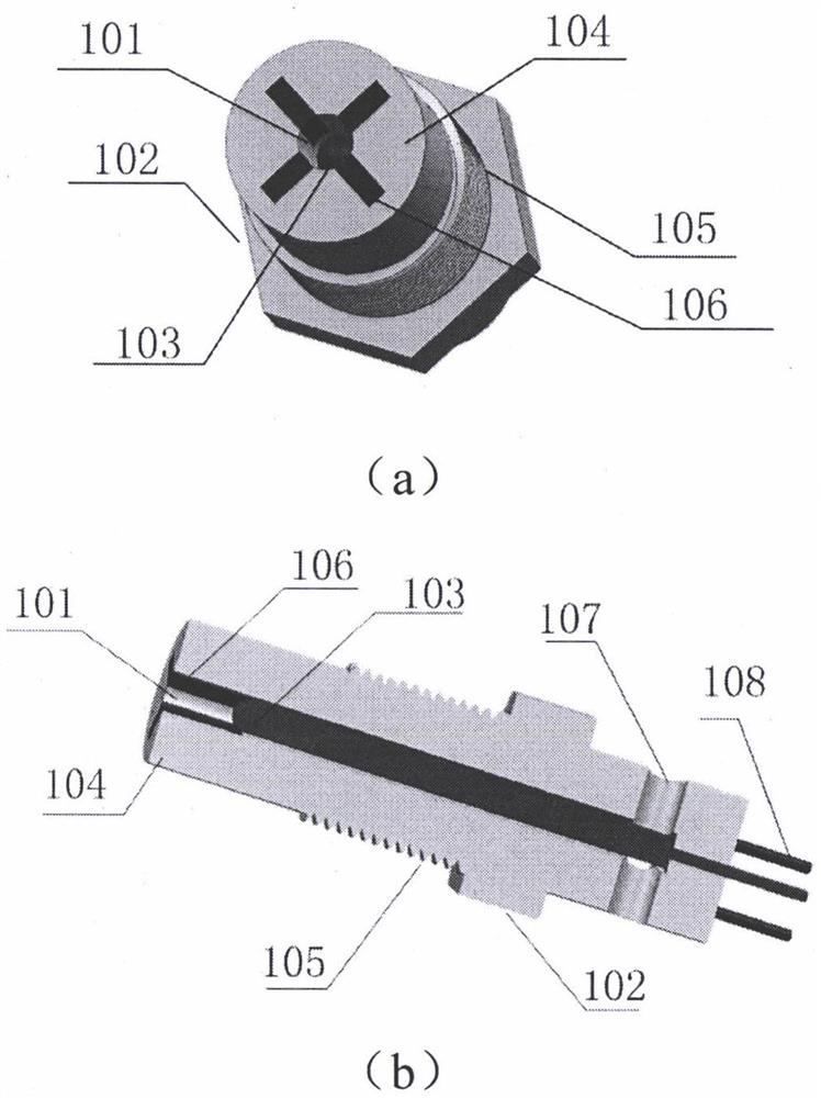
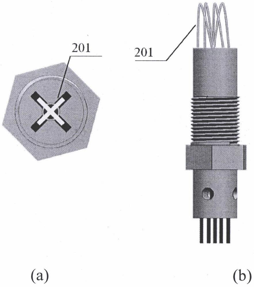
[0042] The main insulator 104 is made of glass-ceramics, and is a cylinder as a whole, with an outer diameter of 12-20mm, preferably 18mm, and a height of 80-200mm, preferably 100mm; the diameter of the jet hole 101 processed inside the main insulator 104 is 4-8mm. Preferably 5mm, the depth is 70-180mm, preferably 90mm; at the bottom of the insulator, four round holes are evenly processed in the circumferential direction as the air inlet 107, with a diameter of 3-8mm, preferably 5mm, and the air inlet communicates with the jet hole 101. The external high-pressure gas enters the igniter through the air inlet 107. On the one hand, it is used to drive the plasma channel to form a sliding arc, and on the other hand, it is used to cool the cathode 106 and the anode 103 to reduce electrode ablation. The cathode 106 is processed by four pieces of high-temperature-resistant metal, preferably metal tungsten, which is connected to the corresponding wire in the lead wire 108 through the s...


PUM

PropertyMeasurementUnit
heightaaaaaaaaaa
diameteraaaaaaaaaa
lengthaaaaaaaaaa

Abstract

Provided is a multi-cathode sliding arc plasma igniter, the shape of which is the same as that of a conventional igniter, and consists of a main insulator (104), an anode (103), a cathode (106), a jet hole (101), a thread (105), a positioning step ( 102), an air inlet (107), and a lead wire (108); when working with the driving power supply, the insulating air between the cathode (106) and the anode (103) is broken down to form a plasma channel, and each cathode ( A plasma discharge channel will be generated between 106) and the anode (103); the high-pressure gas from the external gas source enters the jet hole (101) through the gas inlet hole (107), acts on the plasma discharge channel, and generates a multi-channel driven by the jet Sliding arc discharge. The igniter of the invention changes the original number of cathodes, and cooperates with a certain ignition power source to generate multiple sliding arcs at the same time, effectively improving the energy utilization rate of the power source, increasing the contact area between the plasma and the oil-gas mixture, and increasing the initial ignition core. size, effectively improving the ignition capability of the sliding arc plasma igniter.

Description

technical field [0001] The invention belongs to the design field of aero-engine combustion chambers, and in particular relates to a multi-cathode sliding arc plasma igniter, which is suitable for reliable ignition in aero-engine combustion chambers under extreme conditions at high altitudes. Background technique [0002] When fighter jets are launched in the air, due to reasons such as large maneuvering range and inhalation of exhaust after missile launch, the main combustion chamber will stall. At this time, if a reliable secondary ignition cannot be performed, it is very likely that the fighter plane will be delayed, or the air combat situation will not be reversed as soon as possible, resulting in serious consequences. Therefore, the high-altitude secondary ignition capability of the main combustion chamber of the engine is the main performance index of the engine, which is of great significance for aircraft, especially fighter jets. [0003] At present, the aeroengines ...

Claims


Application Information

Patent Timeline
Patent Type & Authority Patents(China)
IPC IPC(8): F02C7/266
CPCF02C7/266
Inventor 张志波吴云贾敏崔巍朱益飞李军
Owner AIR FORCE UNIV PLA
Learn More