
Control method of compressor, compressor controller and air conditioner unit

A control method and compressor technology, applied in the field of compressor control, compressor controller and air conditioning unit, can solve the problems of compressor position estimation error, inability to accurately detect compressor back electromotive force coefficient, etc.

Inactive Publication Date: 2020-04-17
ZHUHAI GREE REFRIGERATION TECH CENT OF ENERGY SAVING & ENVIRONMENTAL PROTECTION
View PDF6 Cites 8 Cited by
  • Summary
  • Abstract
  • Description
  • Claims
  • Application Information

AI Technical Summary

Problems solved by technology

[0006] Embodiments of the present invention provide a compressor control method, a compressor controller, and an air-conditioning unit to at least solve the technical problem in the related art that the counter electromotive force coefficient of the compressor cannot be accurately detected, resulting in errors in compressor position estimation

Method used


Image

  • Control method of compressor, compressor controller and air conditioner unit
  • Control method of compressor, compressor controller and air conditioner unit
  • Control method of compressor, compressor controller and air conditioner unit

Examples


Embodiment 1

[0038] The compressor controller involved in the following embodiments of the present invention may be a compressor controller with a permanent magnet synchronous motor.

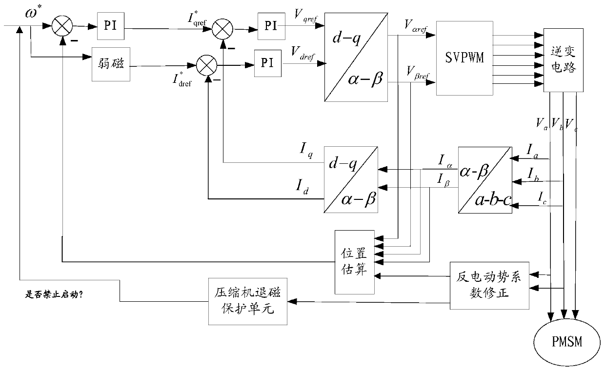
[0039] figure 2 is a schematic diagram of an optional compressor controller according to an embodiment of the present invention, such as figure 2 As shown, on the basis of the prior art, the compressor controller adds a counter electromotive force detection unit and a demagnetization protection unit, wherein the counter electromotive force coefficient correction unit includes:

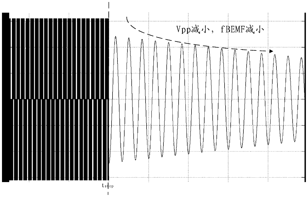
[0040] The back electromotive force detection unit is used to detect the back electromotive force change information when the target motor is running after the drive signal is turned off, wherein the drive signal is used to drive the target compressor to run, and the back electromotive force change information includes at least: peak-peak value of the back electromotive force and back EMF frequency value;

[0041] a back electrom...

Embodiment 2

[0061] How to control the above-mentioned compressor controller will be described below in combination with the control methods of each compressor.

[0062] According to an embodiment of the present invention, an embodiment of a compressor control method is provided. It should be noted that the steps shown in the flow charts of the drawings can be executed in a computer system such as a set of computer-executable instructions, and, Although a logical order is shown in the flowcharts, in some cases the steps shown or described may be performed in an order different from that shown or described herein.

[0063] Figure 6 is a flow chart of an optional compressor control method according to an embodiment of the present invention, such as Figure 6 As shown, the control method includes:

[0064] Step S601, after the drive signal is turned off, detect the back EMF change information when the target motor is running, wherein the drive signal is used to drive the target compressor ...


PUM


Abstract

The invention discloses a control method of a compressor, a compressor controller and an air conditioner unit. The method comprises the steps of detecting back electromotive force change information during operating of a target motor after a drive signal is shut off, wherein the drive signal is used for driving a target compressor to run, and the back electromotive force change information at least comprise peak-peak value of back electromotive force and back electromotive force frequency value; on the basis of the peak-peak value and the back electromotive force frequency value of the back electromotive force, calculating a back electromotive force coefficient of the target motor; and on the basis of a back electromotive force coefficient, determining a construction instruction of the compressor. The technical problems that in the related technology, the back electromotive force coefficient of the compressor cannot be accurately detected, and the position estimation of the compressorhas errors can be solved.

Description

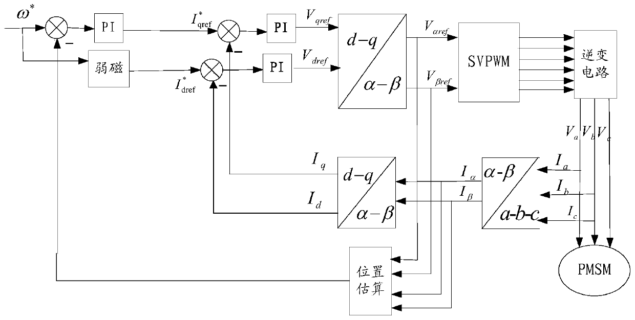
technical field [0001] The invention relates to the technical field of compressor control, in particular to a compressor control method, a compressor controller and an air conditioner unit. Background technique [0002] In the related technology, because the inside of the compressor contains refrigerant oil, refrigerant and other media, its internal environment is harsh, and it is not suitable for installing position sensors. In addition, compressors are mostly used in the home appliance industry, and cost is an important indicator, so the current frequency conversion compressors are mostly used Control without position sensor technology. [0003] A compressor controller using a permanent magnet synchronous motor without a position sensor generally includes a power supply module, an inverter module, a bus voltage detection module, and a current detection module. figure 1 It is an optional permanent magnet synchronous motor and compressor control schematic diagram in the pri...

Claims


Application Information

Patent Timeline
Patent Type & Authority Applications(China)
IPC IPC(8): F04B49/06F25B49/02
CPCF04B49/06F04B49/065F25B49/022
Inventor 程海珍徐常升
Owner ZHUHAI GREE REFRIGERATION TECH CENT OF ENERGY SAVING & ENVIRONMENTAL PROTECTION
Learn More