
Layout method for three-dimensional FPGA chip

A three-dimensional chip and layout technology, applied in special data processing applications, instruments, electrical digital data processing, etc., can solve problems such as improved layout quality, low process reusability, and high software engineering complexity, so as to speed up development progress, The effect of reducing complexity

Active Publication Date: 2020-04-17
HERCULES MICROELECTRONICS CO LTD
View PDF4 Cites 1 Cited by
  • Summary
  • Abstract
  • Description
  • Claims
  • Application Information

AI Technical Summary

Problems solved by technology

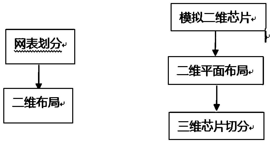
The 3D chip is a brand new 3D chip. In the current EDA tools and design methods, the method followed by the layout of the 3D chip generally uses the method of first dividing the user netlist, and then performing independent secondary processing on the divided netlists. 3D plane layout, this method cannot optimally match the layout of 3D chips, and has the disadvantages that the layout quality needs to be improved, the current process reuse degree is small, and the software engineering complexity is relatively large.

Method used


Image

  • Layout method for three-dimensional FPGA chip
  • Layout method for three-dimensional FPGA chip

Examples


Embodiment Construction

[0024] In order to make the purpose, technical solution and advantages of the present invention clearer, the present invention will be further described in detail below in conjunction with the accompanying drawings. Obviously, the described embodiments are only some of the embodiments of the present invention, rather than all of them. Based on the embodiments of the present invention, all other embodiments obtained by persons of ordinary skill in the art without creative efforts fall within the protection scope of the present invention.

[0025] In the current three-dimensional chip layout, it is generally used to divide the user netlist first, and then carry out independent two-dimensional plane layout on the divided netlist. The present invention proposes a method for three-dimensional chip layout. Chip, carry out two-dimensional plane layout, after the layout result is generated, and then divide the chip, see figure 2 . This 3D chip layout method can better reuse the curr...


PUM


Abstract

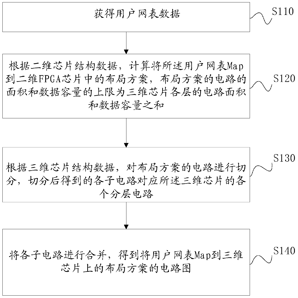
The invention relates to a layout method for three-dimensional FPGA chip design. The method comprises the following steps of: simulating a three-dimensional chip by using a planar layout method of thetwo-dimensional chip and a circuit area and the component capacity of the three-dimensional chip, performing hierarchical division of the three-dimensional chip after a two-dimensional planar layoutresult is generated, and vertically superposing all the divided hierarchical layouts into a three-dimensional chip layout. Compared with an existing method, the method has the advantages that the layout quality is better, and the layout result has more solutions; the main workload is concentrated to a two-dimensional simulation part, so that the complexity of software engineering is reduced; the current software process can be better reused, and the development progress of three-dimensional layout software is accelerated.

Description

technical field [0001] The present invention relates to the technical field of field programmable logic gate array (Field Programmable Gate Array, FPGA) chip layout technology, more specifically, the present invention relates to a method for three-dimensional chip layout. Background technique [0002] FPGA is a logic device composed of many logic units, including gates, look-up tables, and flip-flops. It has rich hardware resources, powerful parallel processing capabilities, and flexible reconfigurable capabilities. It is used in data processing, communications, and networks. It has been widely used in many fields. [0003] The design process of the FPGA chip usually includes: design input, debugging, functional simulation, synthesis, layout and routing, timing simulation, configuration download and other steps. Among them, the layout refers to taking the defined logic and input and output blocks from the map and assigning them to the physical locations inside the FPGA. It ...

Claims


Application Information

Patent Timeline
Patent Type & Authority Applications(China)
IPC IPC(8): G06F30/392G06F30/3308
CPCY02D10/00
Inventor 蒋中华王海力马明
Owner HERCULES MICROELECTRONICS CO LTD
Learn More