
Energy-saving plate-shaped stamping part

An energy-saving technology for stamping parts, applied in the field of energy-saving plate-shaped stamping parts, can solve the problems of single workpiece stamping, easy displacement of stamping, waste of material resources, etc., to achieve the effect of ensuring stability, ensuring precision, and saving costs

Active Publication Date: 2020-04-21
TAIZHOU HUIJIN ELECTRONIC CO LTD
View PDF6 Cites 2 Cited by
  • Summary
  • Abstract
  • Description
  • Claims
  • Application Information

AI Technical Summary

Problems solved by technology

[0003] However, in the past stamping equipment, the workpiece was often stamped alone, and it was necessary to change the angle of the stamping die many times to complete the production of stamping parts. It was necessary to stamp the workpiece at different angles, which wasted a lot of time and increased production. cost, and most of the existing stamping equipment does not have a clamping function, which makes it easy to generate displacement during stamping, which leads to errors and ultimately wastes material resources;

Method used


Image

  • Energy-saving plate-shaped stamping part
  • Energy-saving plate-shaped stamping part
  • Energy-saving plate-shaped stamping part

Examples


Embodiment 1

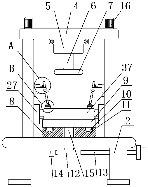
[0025] see figure 1 , figure 2 , image 3 with Figure 4 , an energy-saving plate-shaped stamping part, an energy-saving plate-shaped stamping part, including a base 1; support columns 2 are fixedly connected around the bottom end of the base 1, and the top end of the base 1 passes through a connecting plate 3 It is fixedly connected with the top seat 4; the top seat 4; the bottom end of the top seat 4 is fixedly connected with a hydraulic cylinder 5, and the piston rod 6 of the hydraulic cylinder 5 is fixedly connected with a stamping die 7 by bolts, which is used to press the workpiece body 37 for stamping; workbench 8; said workbench 8 is fixedly connected on the base 1, and the top of said workbench 8 is provided with a lower mold base 9, said lower mold base 9 is provided with a workpiece body 37; height adjustment mechanism; the height adjustment mechanism is connected to the connection plate 3, the height adjustment mechanism includes a motor 16, a threaded rod 17, ...

Embodiment 2

[0037] As a preferred solution of Embodiment 1, please refer to figure 1 , the angle adjustment mechanism includes an annular slide bar 10, an annular chute 11, a rotating shaft 15, a worm gear 12 and a worm 13, an annular chute 11 is opened on the worktable 8, and the bottom end of the lower mold base 9 passes through an annular The slide bar 10 is slidably connected to the annular chute 11, one end of the rotating shaft 15 is fixedly connected to the lower mold base 9, and the other end of the rotating shaft 15 passes through the base 1 and is fixedly connected to the turbine 12, and the worm 13 passes through the mounting seat 14 is rotatably connected to the bottom end of the base 1, and the worm gear 12 is matched with the worm 13;

[0038] One end of the worm 13 is fixedly connected with a rotating handle;

[0039] Wherein, the lower mold base 9 can drive the workpiece body 37 to rotate and adjust the angle by sliding in the annular chute 11 through the annular slide ba...

Embodiment 3

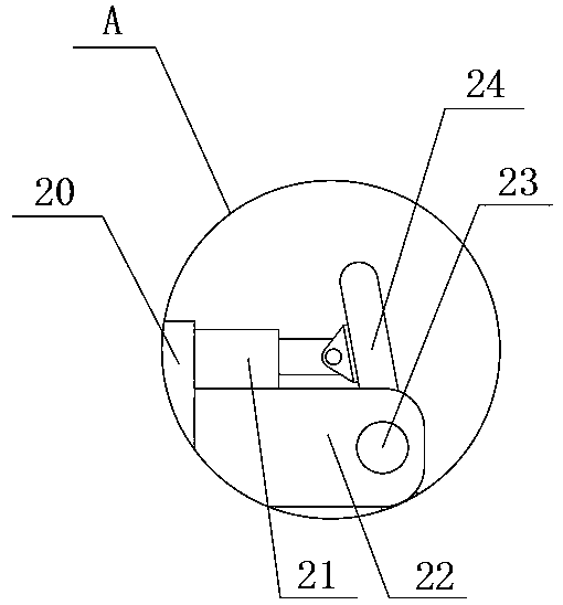
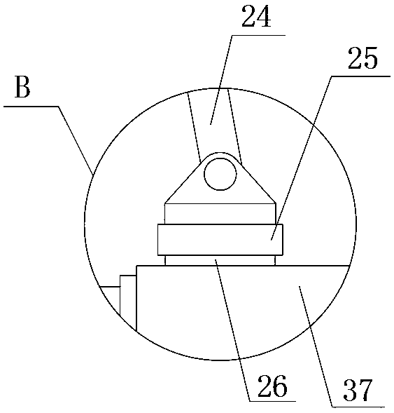
[0042] As a preferred solution of Embodiment 1 or Embodiment 2, please refer to figure 1 with Figure 5 , the shock absorbing mechanism includes a housing 27, a slide plate 28, a connecting column 29, a partition 30, a first spring 31, a second spring 32, an adjusting column 35, a rotating shaft 36, a connecting rod 33 and a rotating column 34, the The housing 27 is fixedly connected to the connecting plate 3 and is located above the workbench 8. The partition plate 30 is fixedly connected in the housing 27, the slide plate 28 is slidably connected in the housing 27, and one end of the adjusting column 35 is connected to the housing 27. The slide plate 28 is fixedly connected, and the other end of the adjustment column 35 passes through the partition 30 and is located between the inner wall of the housing 27 and the partition 30. Two connecting rods 33 are provided, and one end of the two connecting rods 33 The rotating shaft 36 is rotatably connected with the adjustment colu...


PUM


Abstract

The invention relates to an energy-saving plate-shaped stamping part, which comprises a base, a top base, a workbench and a height adjusting mechanism, wherein supporting columns are fixedly connectedto the periphery of the bottom end of the base, and the top end of the base is fixedly connected with the top base by means of a connecting plate; the bottom end of the top base is fixedly connectedwith a hydraulic cylinder, and a piston rod of the hydraulic cylinder is fixedly connected with a stamping die by means of bolts; the workbench is fixedly connected to the base, a lower die base is arranged at the top end of the workbench, and a workpiece body is arranged on the lower die base; the height adjusting mechanism is connected to the connecting plate; and the height adjusting mechanismcomprises a motor, a threaded rod, a strip-shaped notch, an adjusting block and a nut. According to the energy-saving plate-shaped stamping part, the distance between hinge bases can be adjusted according to the height of the stamped workpiece body, the workpiece body can be fully pressed by means of a pressing plate, displacement of the machined part during stamping is avoided, stamping errors are reduced, the precision of the machined workpiece body is guaranteed, resource waste is avoided, and materials are saved.

Description

technical field [0001] The invention relates to the field of stamping equipment, in particular to an energy-saving plate-shaped stamping part. Background technique [0002] Stamping parts are formed by applying external force to plates, strips, pipes and profiles by presses and molds to cause plastic deformation or separation, so as to obtain workpieces of required shape and size. Stamping and forging belong to plastic processing. Collectively known as forging, the stamping blanks are mainly hot-rolled and cold-rolled steel plates and steel strips. The stamping parts are powered by conventional or special stamping equipment, so that the plates are directly deformed and deformed in the mold, so as to obtain certain The production technology of product parts in shape, size and performance, sheet material, mold and equipment are the three elements of stamping processing, stamping processing is a metal cold deformation processing method, it is one of the main methods of metal pl...

Claims


Application Information

Patent Timeline
Patent Type & Authority Applications(China)
IPC IPC(8): B21D22/02B21D43/00B21D37/04F16F15/067F16F3/04
CPCB21D22/02B21D37/04B21D43/003F16F3/04F16F15/067
Inventor 王峰张罗
Owner TAIZHOU HUIJIN ELECTRONIC CO LTD
Learn More