Defocus measurement and control system and method for powder feeding type laser additive manufacturing equipment

A technology of laser additive and manufacturing equipment, applied in the field of additive manufacturing, can solve the problems of reduced flatness of cladding layer, reduced laser beam energy density, reduced powder utilization rate, etc., so as to improve quality, improve measurement and control accuracy, and improve process The effect of stability

Inactive Publication Date: 2020-04-21
XIAN BRIGHT ADDTIVE TECH CO LTD
View PDF7 Cites 1 Cited by
  • Summary
  • Abstract
  • Description
  • Claims
  • Application Information

AI Technical Summary

Problems solved by technology

If the defocus amount is too small, the time for the powder to absorb laser energy is too short, and the powder beam will reach the working plane of the substrate before it is fully converged, which will reduce the utilization rate of the powder, and the protective gas blown by the powder feeding head will make the cladding layer The flatness of the surface is reduced, which eventually leads to a reduction in the quality of the formed surface
If the defocus amount is too large, the distance from the powder feeding head to the working plane will increase, the energy density of the laser beam will decrease, the divergence of the powder beam will become larger, and defects such as pores and incomplete fusion will easily form.

Method used


Image

  • Defocus measurement and control system and method for powder feeding type laser additive manufacturing equipment
  • Defocus measurement and control system and method for powder feeding type laser additive manufacturing equipment

Examples


Embodiment Construction

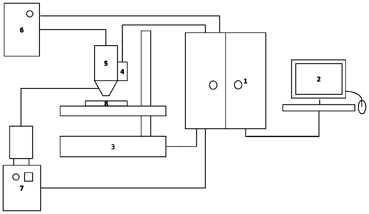
[0023] The defocus measurement and control system for powder-feeding laser additive manufacturing equipment of the present invention has a structure such as figure 1 As shown, it includes computer numerical control system 1, which is bidirectionally connected with human-computer interaction system 2; human-computer interaction system 2 is responsible for program writing, parameter input, and visual display of system status information; The lines are respectively connected to the motion controller 3, the laser controller 6 and the powder feeding controller 7; the powder feeding controller 7 is connected to the powder feeding head 5 through the powder feeding pipeline, the powder feeding head 5 is set facing the working plane 8, and the distance sensor 4 is installed On the side wall of the powder feeding head 5, the distance sensor 4 is bidirectionally connected with the computer numerical control system 1 through the data line; the motion controller 3 is used to control the mov...


PUM


Abstract

The invention discloses a defocus measurement and control system and method for powder feeding type laser additive manufacturing equipment. The defocus measurement and control system comprises a computer numerical control system, wherein the computer numerical control system is bidirectionally connected with a man-machine interaction system and a distance sensor; the man-machine interaction systemis used for compiling programs, inputting parameters and visually displaying system state information; the computer numerical control system is respectively connected with a motion controller, a laser controller and a powder feeding controller through data cables; the powder feeding controller is connected with a powder feeding head through a powder feeding pipeline; the powder feeding head is arranged right opposite to a working plane; the distance sensor is arranged on the side wall of the powder feeding head; and the motion controller is used for controlling the movement of a machine tooland the powder feeding head. According to the defocus measurement and control system and method for the powder feeding type laser additive manufacturing equipment, the defocusing amount of the workingplane and the powder feeding head in the additive manufacturing process can be preset and monitored in real time, the process stability of each layer is improved, and the quality of a powder feedingtype laser additive manufacturing product is further improved.

Description

technical field [0001] The invention belongs to the technical field of additive manufacturing, and relates to a defocus measurement and control system for powder-feeding laser additive manufacturing equipment, and also relates to a defocus measurement and control method. Background technique [0002] The powder-feeding laser additive manufacturing technology uses alloy powder as raw material, rapidly melts and solidifies metal through high-power laser beams, and accumulates layer by layer. The direct near-net blank forming manufacturing of fully dense, high-performance large metal structural parts can be completed directly from the 3D model. Compared with traditional technology, powder-feeding laser additive manufacturing technology has the following advantages: 1. The manufacturing process is highly flexible; 2. The product production cycle is short and the processing speed is fast; 3. The formed parts have excellent comprehensive mechanical properties; 4. The size of the ...

Claims


Application Information

Patent Timeline
Patent Type & Authority Applications(China)
IPC IPC(8): B22F3/105B33Y50/02
CPCB33Y50/02B22F10/00B22F10/25B22F12/90B22F10/31B22F10/36Y02P10/25
Inventor 赵晓明胡广郁明玮
Owner XIAN BRIGHT ADDTIVE TECH CO LTD
Why Eureka
Try Eureka