
Spring end face grinding device and grinding method thereof

An end face and mounting plate technology, applied in the direction of grinding drive device, grinding machine, grinding frame, etc., can solve the problems affecting grinding quality, difference, height position change, etc., so as to improve grinding quality, improve grinding effect, reduce The effect of small radial beating

Inactive Publication Date: 2020-04-21
CHENGDU CHENHUI SPRING MFG
View PDF6 Cites 9 Cited by
  • Summary
  • Abstract
  • Description
  • Claims
  • Application Information

AI Technical Summary

Problems solved by technology

[0004] The above-mentioned existing technical solutions have the following defects. When grinding springs of different sizes, the height of the central axis position of the spring will also be different, and the height position of the contact with the grinding wheel will change, which will affect the grinding quality.

Method used


Image

  • Spring end face grinding device and grinding method thereof
  • Spring end face grinding device and grinding method thereof
  • Spring end face grinding device and grinding method thereof

Examples


Embodiment 1

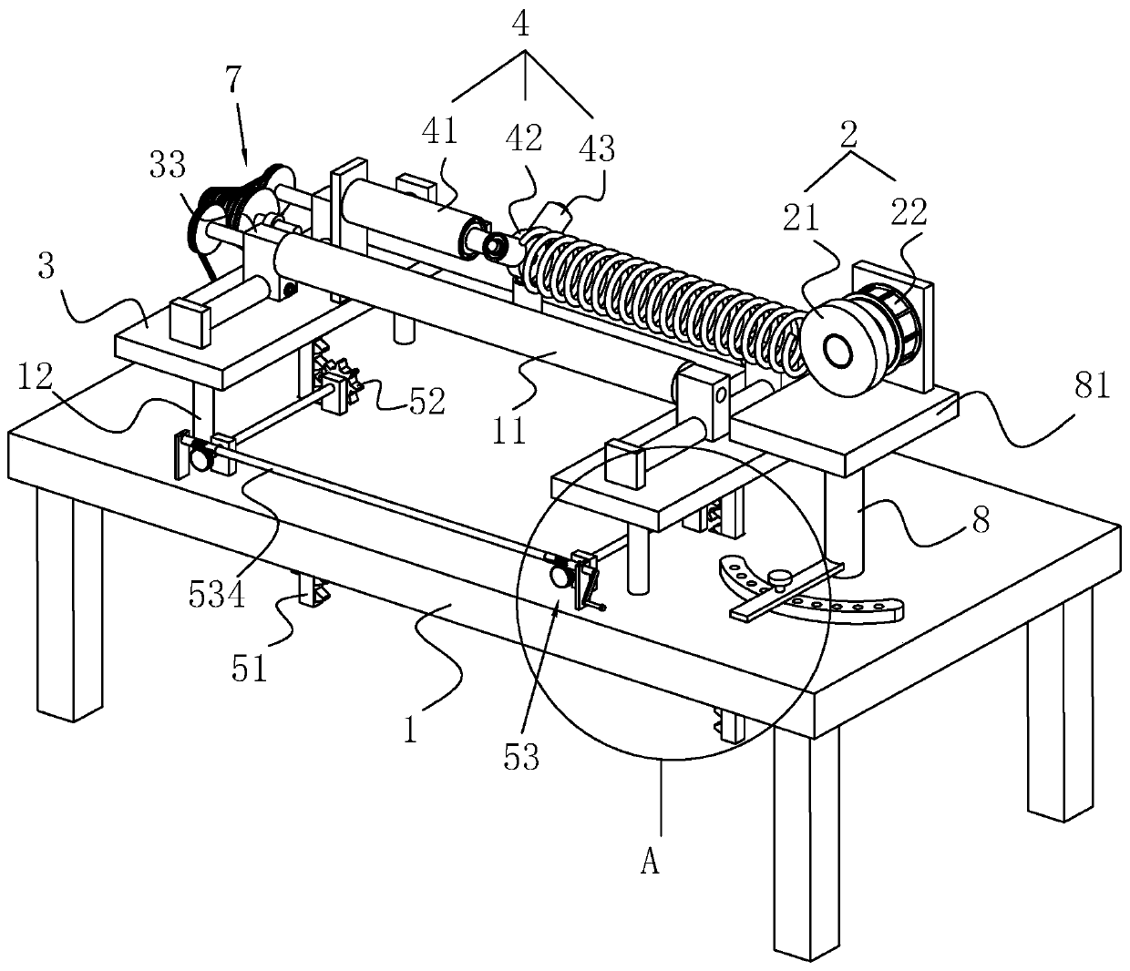
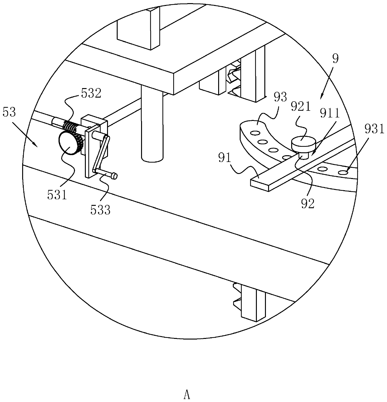
[0045] Such as figure 1 As shown, a spring end face grinding device includes a bottom plate 1 on which a grinding assembly 2 for grinding springs is arranged. The grinding assembly 2 includes a grinding wheel 21 and a rotating motor 22 . The bottom plate 1 is provided with a mounting plate 3, and two mounting plates 3 are arranged in parallel. Two rotating rollers 11 are horizontally arranged on the mounting plate 3 .

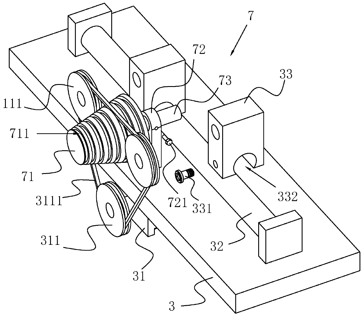
[0046] Such as figure 1 , 3 As shown, the mounting plate 3 is fixedly provided with a guide rail 32 along the axial direction of the rotating roller 11, two guide rails 32 are provided, and the cross section of the guide rail 32 is circular; The bottom wall of the block 33 is provided with a chute 332 adapted to the guide rail 32 ;

[0047] Such as figure 1 , 3 As shown, the rotating roller 11 is rotatably disposed on the mounting block 33, and the mounting block 33 is provided with a limiting member 331 for limiting the position of the mounting block 33;...


PUM


Abstract

The invention relates to a spring end face grinding device and a grinding method thereof, and belongs to the technical field of spring grinding. The spring end face grinding device comprises a bottomplate, wherein a grinding assembly used for grinding a spring is arranged on the bottom plate, and the grinding assembly comprises a grinding wheel and a rotating motor; a mounting plate is arranged on the bottom plate, an abutting assembly used for abutting against one end, away from the grinding assembly, of the spring is arranged on the mounting plate, two rotating rollers are horizontally arranged on the mounting plate, and a driving source for driving the rotating rollers to rotate is arranged on the mounting plate; and a lifting assembly used for driving the mounting plate to ascend anddescend is arranged on the bottom plate. When a larger spring is polished, the mounting plate is driven to move downwards through the lifting assembly to reduce the height of the spring, and then theabutting assembly abuts against the spring; and the height of the spring is adjusted, so that the grinding position of the spring and the center of the grinding wheel are on the same horizontal line,the grinding effect of the grinding wheel on the spring is improved, radial jumping of the spring in the grinding process is reduced, and the grinding quality is effectively improved.

Description

technical field [0001] The invention relates to the technical field of spring grinding, in particular to a spring end surface grinding device and a grinding method thereof. Background technique [0002] After the newly produced spring is cut off, the end face generally has burrs and needs to be polished, and sometimes the end face of the spring needs to be ground even according to the design requirements. At present, the burrs around the end faces of some large springs are manually polished, which requires two people to operate at the same time, one holds a grinder for grinding, and the other keeps turning the spring. This grinding method has certain safety hazards, and the operator is labor-intensive. The grinding efficiency is low. [0003] The Chinese patent with authorized notification number CN 203228083U discloses a spring end face grinding device, which includes a bracket, a spring clamp, a rotating grinding disc, a tray and a pair of slide rails, the tray is arrange...

Claims


Application Information

Patent Timeline
Patent Type & Authority Applications(China)
IPC IPC(8): B24B7/16B24B41/06B24B41/02B24B47/12B24B1/00
CPCB24B1/00B24B7/16B24B41/02B24B41/06B24B47/12
Inventor 何洋朱飞
Owner CHENGDU CHENHUI SPRING MFG
Learn More