Independent cooling device of injection molding machine

An independent cooling and injection molding machine technology, applied in the field of injection molding machines, can solve the problems of inability to use fin coolers with heat dissipation effect, easily damaged fins, cooler impact, etc., to increase the cooling time, save oil consumption, Cooldown increase effect

Pending Publication Date: 2020-04-21
BORCH MACHINERY
View PDF0 Cites 0 Cited by
  • Summary
  • Abstract
  • Description
  • Claims
  • Application Information

AI Technical Summary

Problems solved by technology

This means that the amount of oil and water used (the cooler with a large exchange capacity requires more cooling water) will increase significantly, resulting in greater waste; A large impact will result in the failure to choose a finned cooler with better heat dissipation effect, and the large impact will easily damage the internal fins
[0006] Blindly enlarging the oil tank and choosing a cooling method with a large exchange capacity cooler can no longer meet the needs of the rapid development of injection molding machines.

Method used


Image

  • Independent cooling device of injection molding machine
  • Independent cooling device of injection molding machine
  • Independent cooling device of injection molding machine

Examples


Embodiment Construction

[0032] Below, the present invention will be further described in conjunction with the accompanying drawings and specific implementation methods. It should be noted that, on the premise of not conflicting, the various embodiments described below or the technical features can be combined arbitrarily to form new embodiments. .

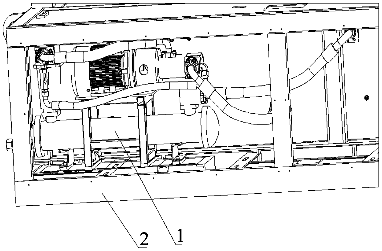
[0033] The invention discloses an independent cooling device 1 of an injection molding machine, which is used for cooling the hydraulic oil of the hydraulic system of the injection molding machine. refer to figure 1 , the independent cooling device 1 is assembled in the frame 2 of the injection molding machine, and is located outside the oil tank of the injection molding machine.

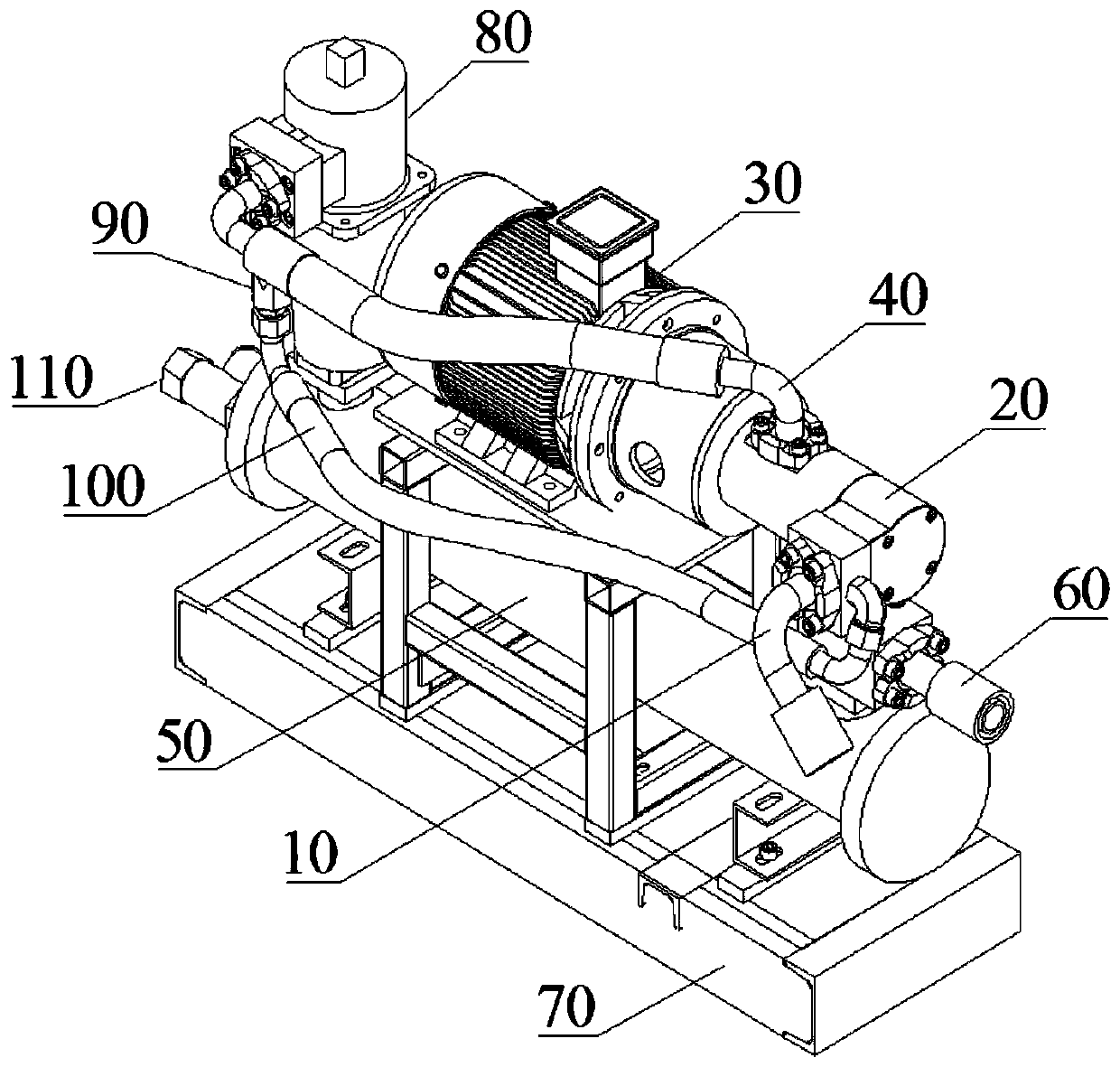
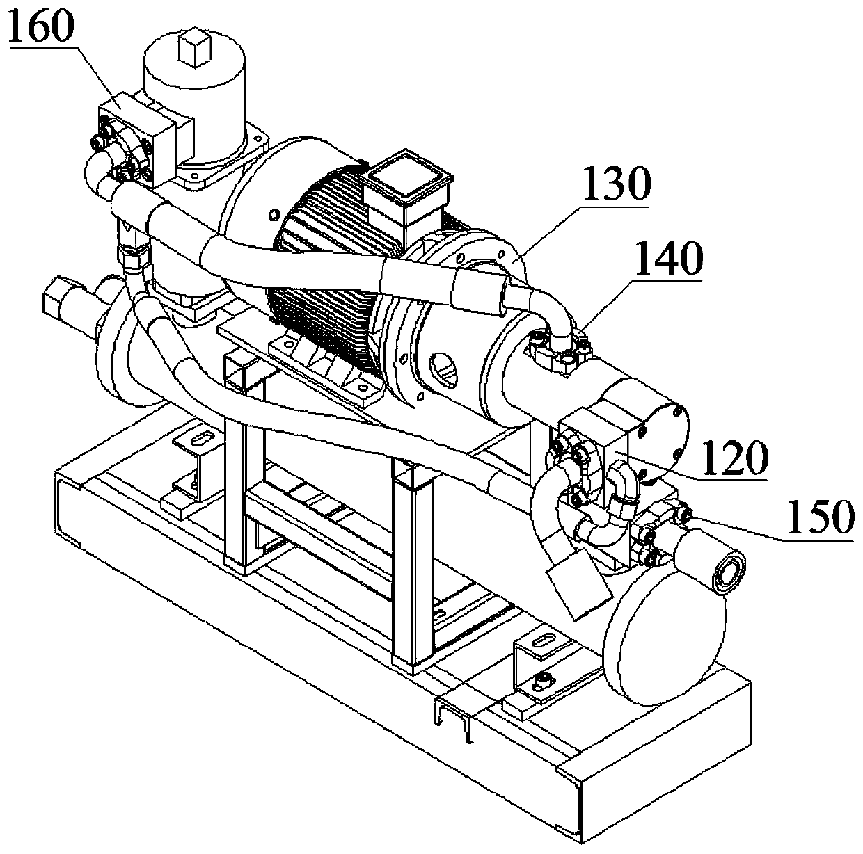
[0034] refer to figure 2 , Figure 4, the present invention includes: screw pump oil suction pipe 10, screw pump 20, motor 30, screw pump oil outlet pipe 40, fin type high-efficiency cooler 50, cooler oil return pipe 60, bracket 70, temperature sensor (not shown), low press...


PUM


Abstract

The invention discloses an independent cooling device of an injection molding machine. The independent cooling device of the injection molding machine comprises a screw pump oil suction pipe, a screwpump, a motor, a screw pump oil outlet pipe, a copper pipe and aluminum fin type efficient cooler (fin type efficient cooler for short), a cooler oil return pipe, a support and a temperature sensor. One end of the screw pump oil suction pipe communicates with an oil tank of the injection molding machine, and the other end of the screw pump oil suction pipe communicates with the screw pump. The motor is connected with the screw pump and drives the screw pump to suck oil. The screw pump communicates with the front end of the fin type efficient cooler through the screw pump oil outlet pipe. The rear end of the fin type efficient cooler communicates with one end of the cooler oil return pipe, and the other end of the cooler oil return pipe communicates with the oil tank. The temperature sensorwhich is used for detecting the temperature of the oil tank is arranged inside the oil tank, and the support is fixedly arranged outside the oil tank of the injection molding machine. By the adoptionof the independent cooling device of the injection molding machine, the cooling time is substantially prolonged, the independent cooling device is not affected by the injection molding technology change any longer, the fin type cooler which is more excellent in heat dissipation performance is selected to enhance the heat dissipation effect, and the oil consumption and the water consumption are reduced.

Description

technical field [0001] The invention relates to the field of injection molding machines, in particular to an independent cooling device of the injection molding machine. Background technique [0002] Injection molding machine, also known as injection molding machine or injection machine, is the main molding equipment for making thermoplastics or thermosetting plastics into various shapes of plastic products using plastic molding molds. The injection molding machine can heat the plastic and apply high pressure to the molten plastic to make it Injection fills the mold cavity. [0003] The process of the injection molding machine can be roughly divided as follows: (1) Clamping stage: the moving platen moves and fits to the fixed platen, so that the mold is closed and locked. (2) Injection stage: It includes two steps of melt glue and glue injection. The raw material of plastic granules enters the injection screw barrel, and a heating device is installed outside the screw barr...

Claims


Application Information

Patent Timeline
Patent Type & Authority Applications(China)
IPC IPC(8): B29C45/72
CPCB29C45/7207B29C2045/7285
Inventor 刘平定黄国良廖俊桦黄基孙晓波李崇德杜呈表
Owner BORCH MACHINERY
Why Eureka
Try Eureka