

Greenhouse film stretching device
A stretching device and film technology, applied in thin material handling, transportation and packaging, flat products, etc., can solve the problems of uneven film pulling force, film tearing, etc., so as to save the need to pick and place multiple films, avoid tear damage effect
- Summary
- Abstract
- Description
- Claims
- Application Information
AI Technical Summary
Problems solved by technology
Method used
Image

Examples
specific Embodiment approach 1
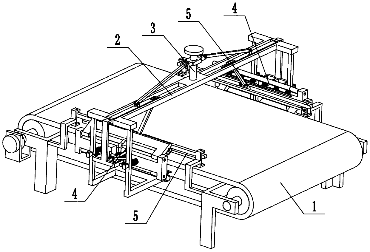
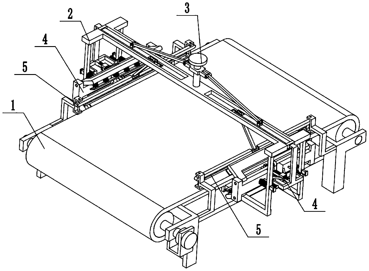
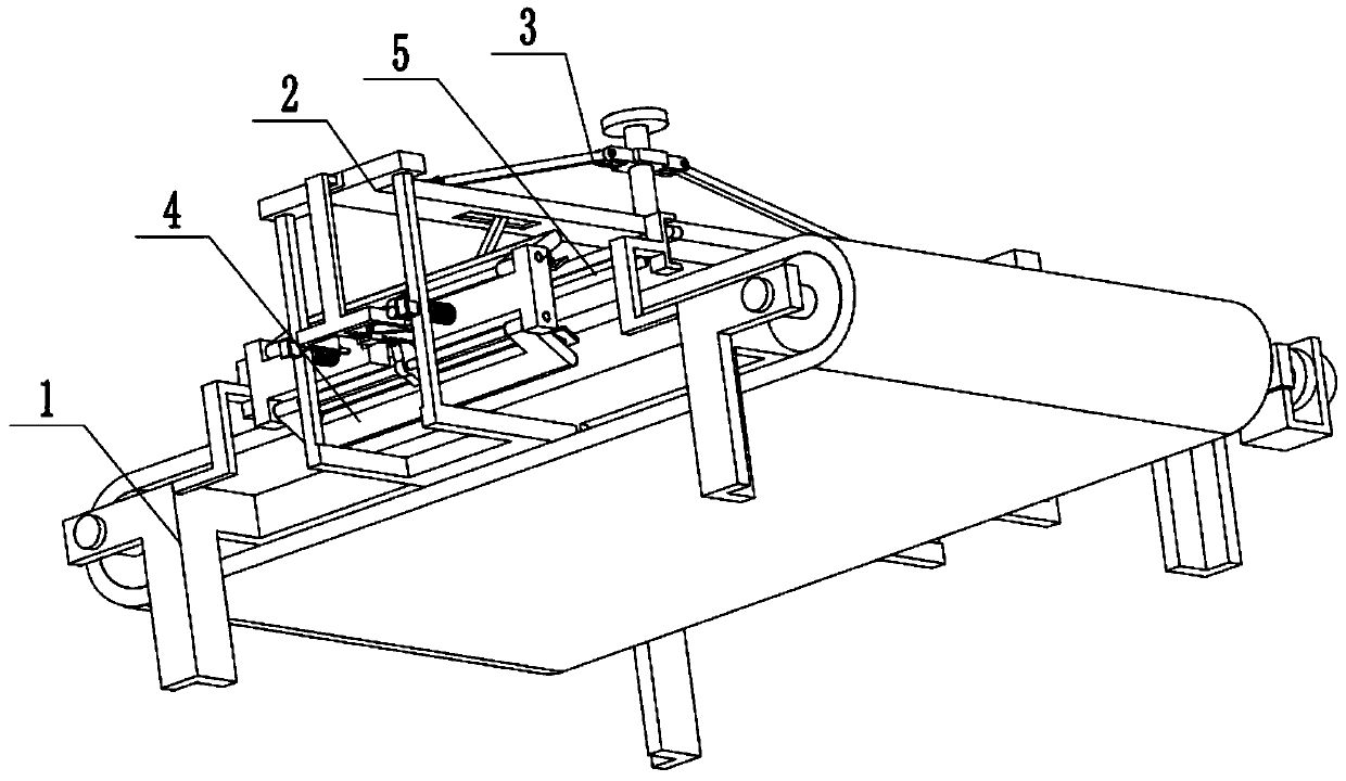
[0028] Combine below Figure 1-9Description of this embodiment, a greenhouse film stretching device, including a film conveying mechanism 1, a support frame assembly 2, a stretch adjustment mechanism 3, a grabbing mechanism 4, and an edge trimming mechanism 5, and the support frame assembly 2 is set on the film conveying On the mechanism 1, the tension adjustment mechanism 3 is connected with the supporting frame assembly 2, and there are two grasping mechanisms 4, and the two grasping mechanisms 4 are symmetrically arranged on the supporting frame assembly 2, and the two grasping mechanisms 4 are all connected to the pulling mechanism 4. The stretch adjustment mechanism 3 is connected, and there are two edge trimming mechanisms 5. The two edge trimming mechanisms 5 are symmetrically arranged on the film conveying mechanism 1, and the two edge trimming mechanisms 5 are all connected with the stretch adjustment mechanism 3. The stretch adjustment mechanism 3 drives the two gras...
specific Embodiment approach 2
[0030] Combine below Figure 1-9 To illustrate this embodiment, the film conveying mechanism 1 includes a motor 1-1, a first rotating shaft 1-2, a second rotating shaft 1-3, a rotating shaft frame 1-4, a roller 1-5 and a conveying belt 1-6; The output shaft of the motor 1-1 is connected to the first rotating shaft 1-2 through a shaft coupling, and the first rotating shaft 1-2 and the second rotating shaft 1-3 are respectively rotated and connected to the two ends of the rotating shaft frame 1-4. The first rotating shaft 1-2 2 and the second rotating shaft 1-3 are respectively fixedly connected with a roller 1-5, and the waste roller 1-5 is connected by transmission belt 1-6; the support frame assembly 2 and the two cutting mechanisms 5 are all located on On the rotating shaft frame 1-4; the conveyor belt 1-6 is located between the two grasping mechanisms 4, and the two trimming mechanisms 5 are located on both sides of the upper end of the conveyor belt 1-6. After the motor 1...
specific Embodiment approach 3
[0032] Combine below Figure 1-9 To illustrate this embodiment, the support frame assembly 2 includes a top frame plate 2-1, a side frame plate 2-2, an upper chute 2-3, a first sliding sleeve 2-4 and a rectangular through groove 2-5; The two ends of the frame plate 2-1 are respectively fixedly connected to a side frame plate 2-2, and the two side frame plates 2-2 are respectively fixedly connected to the two ends of the rotating shaft frame 1-4, and the two grasping mechanisms 4 are respectively provided with On the two side frame plates 2-2; the upper end of the top frame plate 2-1 is provided with two upper chute 2-3, and the lower end of the two upper chute 2-3 is respectively provided with a rectangular through groove 2- 5, the outer ends of the two upper chute 2-3 are respectively fixedly connected with a first sliding sleeve 2-4; the stretch adjustment mechanism 3 is arranged on the top frame plate 2-1.
PUM
 Abstract
Description
Claims
Application Information