Textile chemical dyeing and finishing equipment

A chemical and textile technology, applied in the field of textile chemical dyeing and finishing equipment, can solve the problems of textile fabric fading and oxidation, affecting the effect of textile fabric forming, and reducing the service life of equipment

Inactive Publication Date: 2020-04-21
储小英
View PDF0 Cites 4 Cited by
  • Summary
  • Abstract
  • Description
  • Claims
  • Application Information

AI Technical Summary

Problems solved by technology

[0002] In the process of textile dyeing, since the dyed textile cloth is still driven by some rotating drums to be rolled or directly dried and dried after the dyeing process, there are many problems in the process, such as: Since the textile fabric just coming out of the dyeing process contains a lot of water, it will drip onto the ground or equipment during continuous transportation. If it is some acid-base dye solution, it will damage the ground and equipment, which reduces the service life of the equipment, and due to continuous transportation, the textile fabric will be in contact with the air more, and the dyes in the textile fabric will be easily oxidized, which will greatly affect the molding effect of the textile fabric. , which reduces the quality of the product, and when the finished textile fabric is loaded, it is directly rolled into a roll and then covered with a protective film to protect the rolled textile fabric, but there are many air gaps in the textile fabric between different layers , it will also fade and oxidize the textile fabric after a long time, which is not conducive to long-term storage and transportation

Method used


Image

  • Textile chemical dyeing and finishing equipment
  • Textile chemical dyeing and finishing equipment
  • Textile chemical dyeing and finishing equipment

Examples


Embodiment Construction

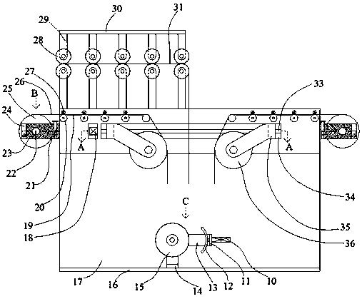
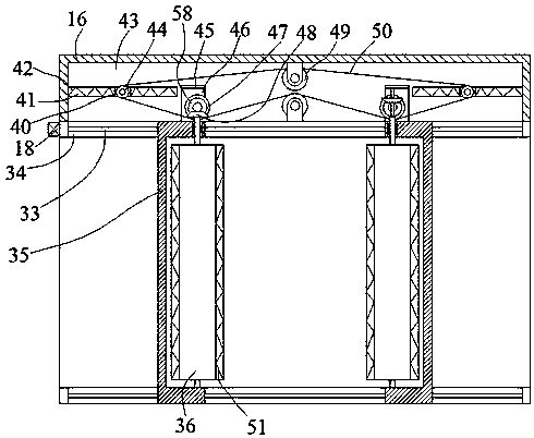
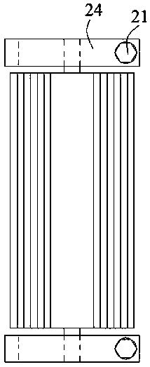
[0021] Such as Figure 1-Figure 4 As shown, the present invention is described in detail. For the convenience of description, the orientations mentioned below are now stipulated as follows: figure 1The up, down, left, right, front and back directions of the projection relationship are consistent. A textile chemical dyeing and finishing equipment of the present invention includes a box body 16, an open inner cavity 17 is arranged in the box body 16, and the rear end wall of the inner cavity 17 communicates with A front-rear symmetrical sliding cavity 34 is provided, and a rear side cavity 43 is communicated with the rear end wall of the sliding cavity 34 on the rear side. The sliding cavity 34, the rear side cavity 43 and the inner cavity 17 A mobile extruding device capable of adjusting left and right and extruding the weaving steps is provided. Release devices for releasing the protective film are provided on both sides of the box body 16. The woven fabric with the protectiv...


PUM


Abstract

The invention discloses textile chemical dyeing and finishing equipment, which comprises a box body, wherein an open inner cavity is formed in the box body, sliding inner cavities symmetrically arranged front and back are formed in the rear end wall of the inner cavity in a communicating mode, a rear side cavity is formed in the rear end wall of the sliding inner cavity in the rear side in a communicating manner, the sliding inner cavities, the rear side cavity and the inner cavity are internally provided with movable extrusion devices capable of being adjusted left and right and extruding a textile cloth, release devices for releasing a protective film are arranged on the two sides of the box body, a bottom coiling device for further coiling the textile cloth attached with the protectivefilm is fixedly arranged in the lower end wall of the inner cavity, and the upper end surface of the box body is provided with a leading-in device for leading an textile cloth in an external space into the equipment. The equipment has smart structure, can protect a textile cloth and prevent the textile cloth from being oxidized compared with the equipment in the prior art, has the improved workingefficiency through the smart structure of the equipment, and has the prolonged service life.

Description

technical field [0001] The invention relates to the technical field of textile equipment, in particular to textile chemical dyeing and finishing equipment. Background technique [0002] In the process of textile dyeing, since the dyed textile cloth is still driven by some rotating drums to be rolled or directly dried and dried after the dyeing process, there are many problems in the process, such as: Since the textile fabric just coming out of the dyeing process contains a lot of water, it will drip onto the ground or equipment during continuous transportation. If it is some acid-base dye solution, it will damage the ground and equipment, which reduces the service life of the equipment, and due to continuous transportation, the textile fabric will be in contact with the air more, and the dyes in the textile fabric will be easily oxidized, which will greatly affect the molding effect of the textile fabric. , which reduces the quality of the product, and when the finished tex...

Claims


Application Information

Patent Timeline
Patent Type & Authority Applications(China)
IPC IPC(8): B32B37/10
CPCB32B37/10
Inventor 储小英
Owner 储小英
Why Eureka
Try Eureka