Underwater robot laying device

An underwater robot and robot technology, applied in underwater operation equipment, transportation and packaging, ship parts, etc., can solve problems such as inability to make predictions in advance, high requirements for operators, and difficult implementation, and achieve simple structure , the method is flexible and changeable, and the effect of reducing risks

Inactive Publication Date: 2020-04-21
中国船舶重工集团有限公司第七一0研究所
View PDF9 Cites 1 Cited by
  • Summary
  • Abstract
  • Description
  • Claims
  • Application Information

AI Technical Summary

Problems solved by technology

[0002] At present, the deployment of underwater robots usually adopts manual intervention. There are two main methods: one is to lift the underwater robot to the deployment point and use a slender rod tool to separate the hook from the underwater robot. This method has high requirements on sea conditions and operators, and is generally only suitable for lakes or under good sea conditions, and the operator of the slender rod tool must undergo practical training and master certain skills before he can be competent. It is difficult to implement and requires high requirements.
Another way is to use the transfer method to extend the manual control end to the shore or deck for operation. Since the movement of the underwater robot during deployment has certain randomness, it is impossible to make a prediction in advance, and it needs to be set up throughout the process. A special person is assigned to protect and operate the manual control end. If there is a slight carelessness, accidents such as misoperation may occur, and there are certain safety risks.

Method used


Image

  • Underwater robot laying device
  • Underwater robot laying device
  • Underwater robot laying device

Examples


Embodiment Construction

[0020] The present invention will be described in detail below with reference to the accompanying drawings and examples.

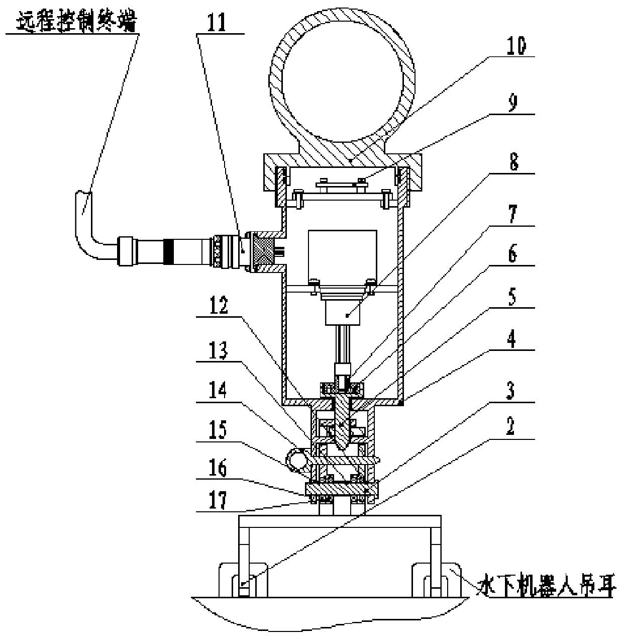
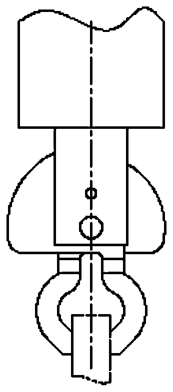
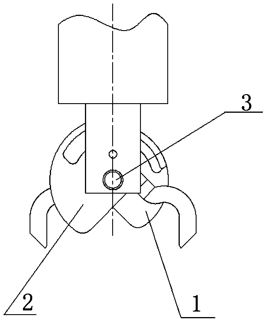
[0021] This embodiment provides an underwater robot deployment device, such as figure 1 As shown, it includes right clip hook 1, left clip hook 2, sealing cylinder, fixed shaft 3, release shaft 5, linear motor 8, motor control board 9, watertight connector 11, right snap ring 12, middle snap ring 13, left Snap ring 15, positioning snap ring 16, stainless steel bearing 17 and positioning pin 14.

[0022] The sealing cylinder includes a sealing cylinder 4 and a sealing end cover 10. The sealing cylinder 4 provides installation and sealing space for the linear motor 8 and the motor control board 9. The sealing cylinder 4 is designed with an installation interface for the linear motor 8 and the motor control board 9 , to ensure that the installation is firm and reliable. The sealing cylinder 4 is a cylinder with one end open, and the open end is threadedly c...


PUM


Abstract

The invention discloses an underwater robot laying device which comprises a sealing cylinder, a linear motor, a release shaft, a fixing shaft, a left clamping hook and a right clamping hook; the linear motor is mounted in the sealing cylinder; a linear motor telescopic rod is in clearance fit with one end of the release shaft; the upper end of the left clamping hook and the upper end of the rightclamping hook are vertically staggered, meanwhile, the left clamping hook and the right clamping hook are rotationally connected to the sealing cylinder through the fixing shaft, the other end of therelease shaft is in sliding fit with butt joint holes in the upper portions of the left clamping hook and the right clamping hook to limit rotation of the left clamping hook and the right clamping hook, and at the moment, the left clamping hook and the right clamping hook jointly clamp external robot lugs. During laying, the linear motor telescopic rod is used for driving the release shaft to moveupwards in the axial direction, the release shaft is separated from the left clamping hook and the right clamping hook, the left clamping hook and the right clamping hook rotate around the fixing shaft under the action of self gravity and then are opened, the external robot lifting lugs are released, and laying is completed. The device is simple in structure, convenient to install and high in reliability.

Description

technical field [0001] The invention relates to the technical field of underwater robot deployment and recovery, in particular to an underwater robot deployment device. Background technique [0002] At present, the deployment of underwater robots usually adopts manual intervention. There are two main methods: one is to lift the underwater robot to the deployment point and use a slender rod tool to separate the hook from the underwater robot. This method has high requirements on sea conditions and operators, and is generally only suitable for lakes or under good sea conditions, and the operator of the slender rod tool must be competent after practical training and mastering certain skills, which is difficult to implement and requires high requirements. Another way is to use the transfer method to extend the manual control end to the shore or deck for operation. Since the movement of the underwater robot during the deployment process has certain randomness, it is impossible to...

Claims


Application Information

Patent Timeline
Patent Type & Authority Applications(China)
IPC IPC(8): B63C11/52B63B17/00B66C13/08
CPCB63B17/00B63C11/52B66C13/08
Inventor 牛群峰张帆韩峰刘峡彭阿静
Owner 中国船舶重工集团有限公司第七一0研究所
Why Eureka
Try Eureka