Variable cycle engine

A technology of variable cycle engines and combustion chambers, which is applied in the direction of machines/engines, ramjet engines, mechanical equipment, etc. It can solve the problems of airflow blockage in the turbine chamber, decrease in compressor power, and increase in wind resistance, so as to reduce parts and weight, Increase ceiling and top speed, avoid surge effect

Active Publication Date: 2020-04-21
罗辉
View PDF10 Cites 0 Cited by
  • Summary
  • Abstract
  • Description
  • Claims
  • Application Information

AI Technical Summary

Problems solved by technology

[0003] The existing engines have the following problems: 1. If the engine output power needs to be increased, refueling can only be carried out in the core combustion chamber 10 and the afterburner 20, and too much refueling in the core combustion chamber 10 will cause the temperature of the combustion chamber to increase significantly. Raise, the turbine material is unbearable
2. Due to the fixed matching relationship between the turbine and the compressor, the engine cannot adapt to the huge wind pressure changes at high and low speeds during flight, and engine surge is unavoidable
3. Refueling in the afterburner 20 will greatly reduce the thermal-dynamic conversion ratio of fuel (large fuel consumption), slow down the airflow blockage in the turbine chamber, cause the temperature of the turbine to continue to rise, and slow down the airflow in the turbine chamber to reduce the output power of the turbine, which in turn leads to The reduction of compressor power and fan power directly leads to the decrease of the overall air flow of the engine and the increase of wind resistance
In short, the existing turbofan engine design has small potential for engine power adjustment, high fuel consumption and unstable performance, which is not suitable for changing flight environments

Method used


Image

  • Variable cycle engine
  • Variable cycle engine

Examples


Embodiment Construction

[0014] The technical solution of the present invention will be described in detail below through specific examples.

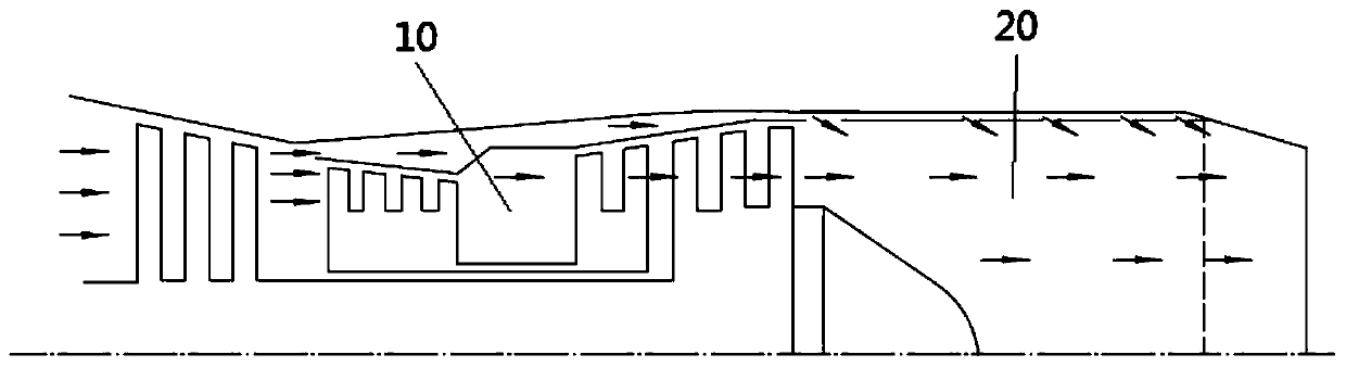
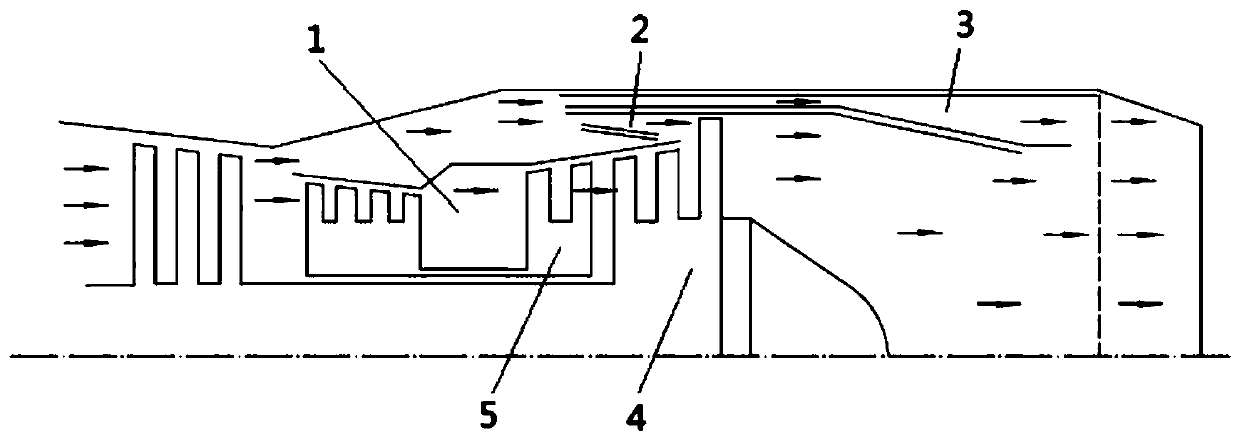
[0015] Such as figure 2 As shown, the variable cycle engine includes a first combustion chamber 1, a second combustion chamber 2 and a third combustion chamber 3 which are independent respectively, the first combustion chamber 1 is a core combustion chamber, and the second combustion chamber 2 is located outside the high-pressure turbine 5, The thermally expanded airflow combusted in the second combustion chamber 2 flows through the blade with the largest outer diameter at the rear end of the low-pressure turbine 4 , and the third combustion chamber 3 is located outside the second combustion chamber 2 and adopts a scram combustion chamber. The first combustion chamber 1, the second combustion chamber 2 and the third combustion chamber 3 adopt low-pressure evaporator auxiliary combustion (the evaporator is not shown in the figure), by adjusting the first combus...


PUM


Abstract

The invention provides a variable cycle engine. The engine comprises a first combustion chamber, a second combustion chamber and a third combustion chamber which are independent, wherein the first combustion chamber is a core combustion chamber, the second combustion chamber is positioned on an outer side of a high-pressure turbine, thermal expansion airflow combusted in the second combustion chamber flows through a blade with the largest outer diameter at a rear end of the low-pressure turbine, the third combustion chamber is positioned outside the second combustion chamber, a scramjet combustion chamber is adopted, the first combustion chamber, the second combustion chamber and the third combustion chamber adopt low-pressure evaporators for auxiliary combustion, a thermodynamic cycle ratio of an engine turbine to a compressor is adjusted by adjusting oil supply of the first combustion chamber, the second combustion chamber and the third combustion chamber, engine surge is avoided, the working temperature of the turbine can be actively adjusted and controlled at any time instead of being originally uncontrollable, and the engine rise limit and the highest speed are greatly increased. The engine is advantaged in that the turbofan engine and the scramjet engine can be integrated into a whole at the same time under the condition that parts and the weight are reduced.

Description

technical field [0001] The invention relates to the technical field of axial flow engines, in particular to a variable cycle engine. Background technique [0002] Such as figure 1 As shown, in the design structure of the existing common axial-flow turbofan engine, the high-pressure airflow after combustion in the core combustion chamber 10 first drives the two-layer high-pressure turbine, and the high-pressure turbine is linked to the high-pressure compressor to rotate, and then passes through the low-pressure turbine, and the low-pressure turbine is linked. The low pressure fan turns, followed by the afterburner 20 . The principle is to expand the air entering the engine through fuel combustion in the core combustion chamber 10, part of the kinetic energy of the expanded airflow is directly the output force of the engine, and the other part of the kinetic energy drives the turbine, and the turbine drives the compressor and the fan, so that the external air continuously flo...

Claims


Application Information

Patent Timeline
Patent Type & Authority Applications(China)
IPC IPC(8): F02C3/14F02C3/06F02K7/14
CPCF02C3/06F02C3/14F02K7/14
Inventor 罗辉
Owner 罗辉
Why Eureka
Try Eureka