Hydraulic high-pressure particle jet plug drilling test device

A test device and particle technology, applied in the field of oil drilling and production, can solve the problems of stuck drilling accident, drill bit milling casing, casing damage, etc., and achieve the effects of reliable dynamic sealing, optimized construction parameters, and adjustable WOB.

Active Publication Date: 2020-04-21
CHINA UNIV OF PETROLEUM (EAST CHINA)
View PDF12 Cites 0 Cited by
  • Summary
  • Abstract
  • Description
  • Claims
  • Application Information

AI Technical Summary

Problems solved by technology

The other is to drill through the downhole screw rod and drill bit. In this method, the pressurization of the drill bit is difficult, and the effect of the drill plug is not ideal.
For wells with casing damage and severe casing deformation, conventional screw drilling tools and drill bits are difficult to pass through smoothly

Method used


Image

  • Hydraulic high-pressure particle jet plug drilling test device
  • Hydraulic high-pressure particle jet plug drilling test device
  • Hydraulic high-pressure particle jet plug drilling test device

Examples


Embodiment Construction

[0015] The present invention will be further described below in conjunction with accompanying drawing:

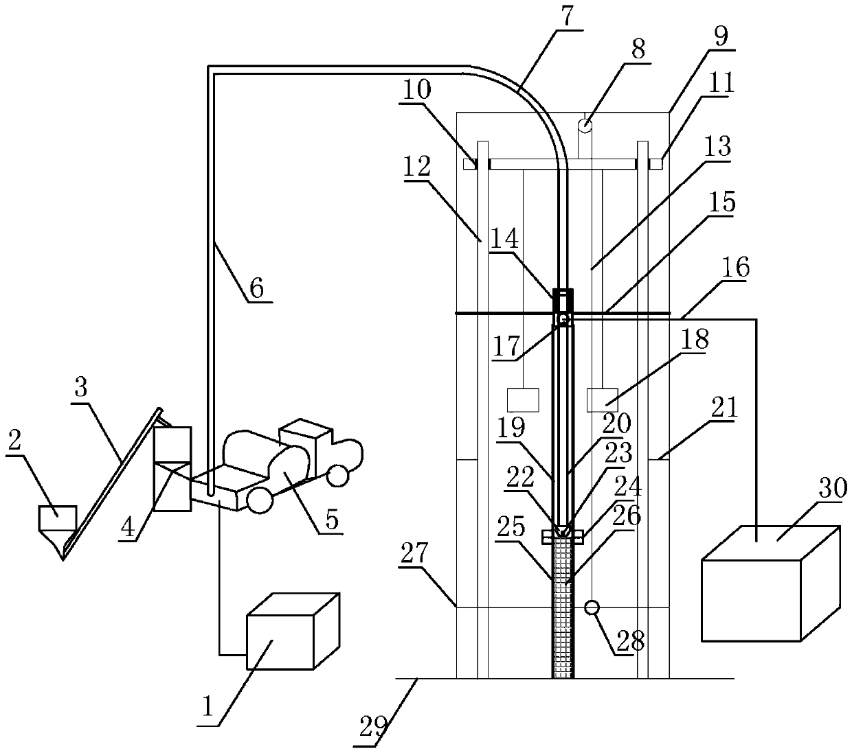
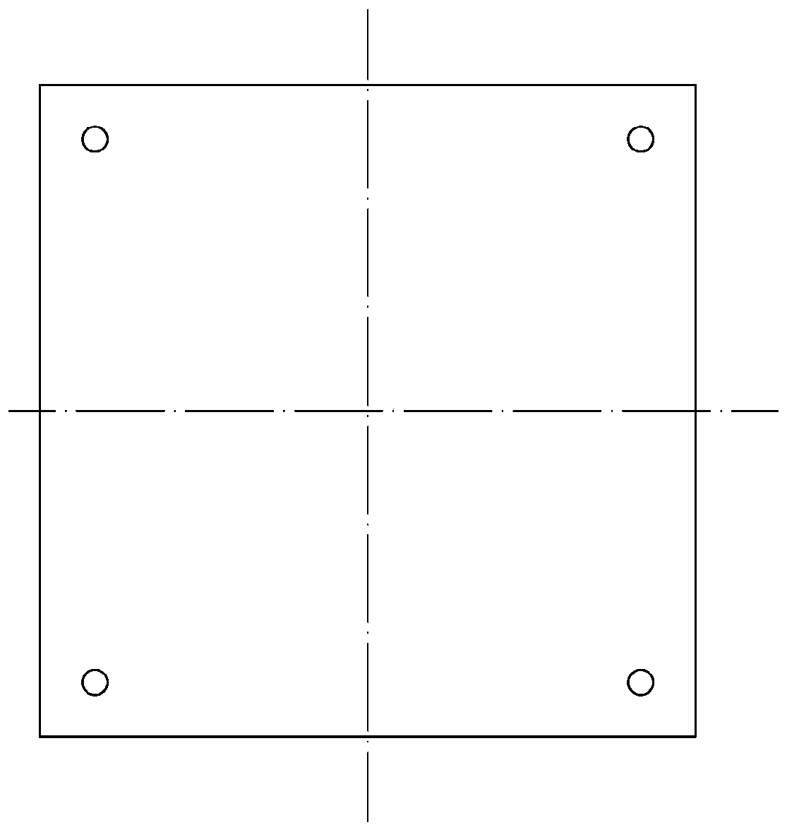
[0016] like Figure 1~3As shown, the hydraulic high-pressure particle jet drilling plug test device of the present invention includes a storage tank 1, a sand mixing cylinder 2, a conveyor 3, a material receiving cylinder 4, a cement truck 5, a high-pressure pipe 6, a high-pressure elbow 7, and a pulley 8. Skid mounting frame 9, sliding sleeve 10, moving beam 11, vertical rail 12, steel wire rope 13, sliding seal assembly 14, centralizing rod 15, return pipeline 16, return liquid port 17, counterweight 18, glass Upper cylinder 19, oil pipe 20, middle beam 21, nozzle 22, nozzle 23, flange plate 24, glass lower cylinder 25, cement plug 26, bottom beam 27, hinge 28, base 29, recovery tank 30. The storage tank 1 is arranged on the ground for storing circulating fluid and supplying liquid for the cement truck 5. The sand mixing tank 2 is arranged at the front of the cement truc...


PUM


Abstract

The invention belongs to the field of petroleum drilling and production. The invention particularly relates to a hydraulic high-pressure particle jet plug drilling test device. The device comprises aconveyor, a cementing truck, a high-pressure pipe, a skid-mounted frame, a sliding sleeve, a movable cross beam, a vertical rail, a sliding sealing assembly, a return pipeline, a balancing weight, anupper glass cylinder, an oil pipe, a spray head, a nozzle, a lower glass cylinder, a hinge, a recovery tank and the like, the special particle jet drilling and plugging test device is used, the groundfull-size simulation of the underground particle jet drilling and plugging process is realized; by means of visualization of particle jet flow jet drilling and annulus upward returning, lowering andlifting of a spray head can be effectively controlled, due to adjustable bit pressure in the drilling process and reliable dynamic sealing of a moving oil pipe and annulus return liquid, the hydraulichigh-pressure particle jet flow plug drilling effect is verified, and hydraulic high-pressure particle jet flow plug drilling optimization construction parameters are obtained.

Description

technical field [0001] The invention relates to a hydraulic high-pressure particle jet drilling plug test device, which belongs to the field of petroleum drilling. Background technique [0002] With the continuous deepening of oilfield development, in order to meet the production needs, technological constructions such as plugging and sealing layers, cement plugging blastholes, oil and water well inspection and plugging, and long-term shutdown wells to resume production are gradually increasing. During the construction of these technologies, cement will be produced. The plug surface needs to be drilled out through plug drilling operations. There are two commonly used plug drilling methods at present. One is to drive the downhole drill bit to rotate through the wellhead rotary table. This method requires major overhaul of operating equipment and high investment costs. Another kind is to add drill bit drilling mode by downhole screw rod, the pressurization of this method drill...

Claims


Application Information

Patent Timeline
IPC IPC(8): G09B25/00G09B25/02
CPCG09B25/00G09B25/02
Inventor 赵健常方瑞韩晓强徐依吉张在朋张宪超李延伟刘宝欣郭文卿
Owner CHINA UNIV OF PETROLEUM (EAST CHINA)
Why Eureka
Try Eureka