Direct-current transformer

A technology of DC transformers and transformers, which is applied in the direction of converting DC power input to DC power output, instruments, and adjusting electrical variables, etc. It can solve the problems of large quality and occupied area of ​​DC transformer, small quality and occupied area, and high cost. problem, to achieve the effect of low cost, small quality and small occupied area, and reduced occupied area

Pending Publication Date: 2020-04-21
CHINA EPRI ELECTRIC POWER ENG CO LTD +1
View PDF0 Cites 0 Cited by
  • Summary
  • Abstract
  • Description
  • Claims
  • Application Information

AI Technical Summary

Problems solved by technology

[0005] In order to overcome the shortcomings of the above-mentioned DC transformers in the prior art, which are relatively large in quality and occupying an area, and high in cost, the present invention provides a DC transformer, which is located between the low-voltage DC bus and the medium-voltage DC bus, and includes a plurality of DC transformers Subunits; the input terminals of multiple DC transformer subunits are connected in sequence and connected to the low-voltage DC bus; the output terminals of multiple DC transformer subunits are connected sequentially and connected to the medium voltage DC bus; the DC transformer subunits include DC / DC converter and fault isolation voltage equalization module; the input end of the DC / DC converter is connected to the low-voltage DC bus, the output end is connected to the input end of the fault isolation voltage equalization module, and the output end of the fault isolation voltage equalization module is connected to the medium voltage DC Busbar; fault isolation voltage equalization module is used to isolate faults from high-voltage DC busbars / low-voltage DC busbars, and realize voltage equalization, with small quality and small footprint, and low cost

Method used


Image

  • Direct-current transformer
  • Direct-current transformer
  • Direct-current transformer

Examples


Embodiment 1

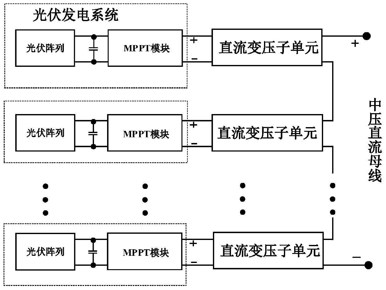
[0045] Embodiment 1 of the present invention provides a DC transformer, such as figure 2 As shown, it is located between the low-voltage DC bus and the medium-voltage DC bus, which includes a plurality of DC transformer subunits; Embodiment 1 of the present invention uses k DC transformer subunits;

[0046] The input ends of the k DC transformer subunits are connected sequentially and connected to the low-voltage DC bus; the output terminals of the k DC transformer subunits are connected sequentially and connected to the medium voltage DC bus; specifically: the k DC transformer subunits The input ends are connected in parallel, and the output ends are connected in series.

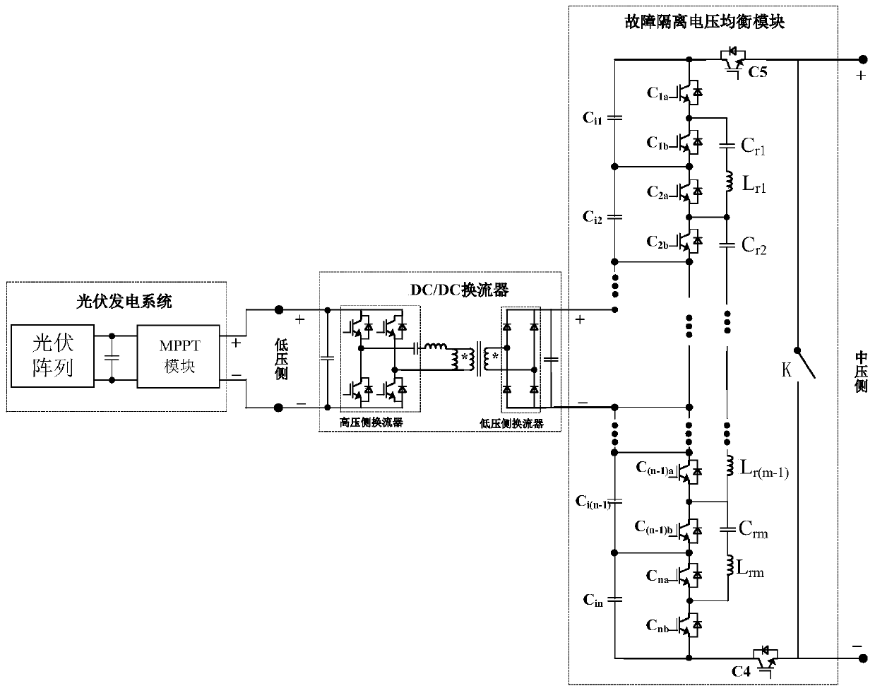
[0047] Such as figure 1 As shown, the DC transformation subunit includes a DC / DC converter and a fault isolation voltage equalization module;

[0048] The input end of the DC / DC converter is connected to the low-voltage DC bus, the output end is connected to the input end of the fault isolation voltage e...

Embodiment 2

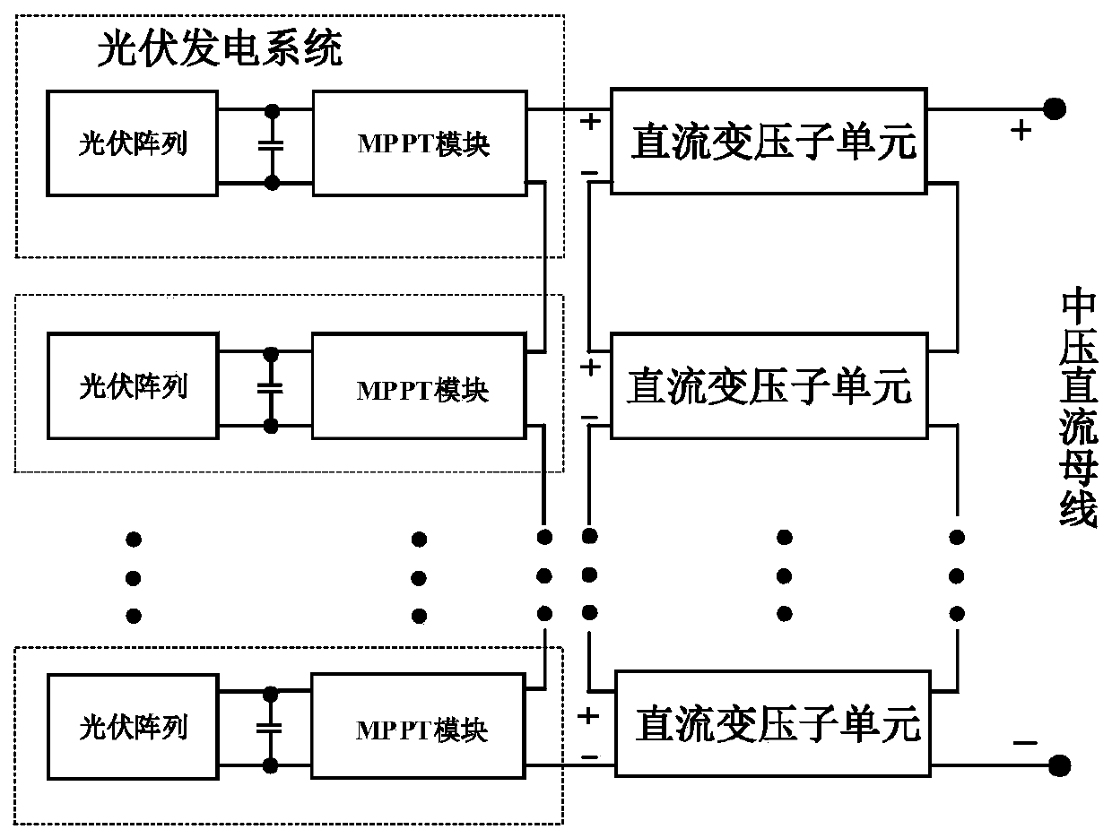
[0070] Embodiment 2 of the present invention provides a DC transformer, such as image 3 As shown, it is located between the low-voltage DC bus and the medium-voltage DC bus, which includes a plurality of DC transformer subunits; Embodiment 2 of the present invention includes k DC transformer subunits;

[0071] The input terminals of the k DC transformer subunits are connected sequentially, and connected to the low-voltage DC bus; the output terminals of the k DC transformer subunits are connected sequentially, and connected to the medium voltage DC bus; specifically, the input terminals of the k DC transformer subunits Both the terminal and the output terminal are connected in series.

[0072] Such as figure 1 As shown, the DC transformation subunit includes a DC / DC converter and a fault isolation voltage equalization module;

[0073] The input end of the DC / DC converter is connected to the low-voltage DC bus, the output end is connected to the input end of the fault isolat...


PUM


Abstract

The invention provides a direct-current transformer which is located between a low-voltage direct-current bus and a medium-voltage direct-current bus and comprises a plurality of direct-current voltage transformation subunits. The input ends of a plurality of direct-current voltage transformation subunits are connected in sequence and are connected with the low-voltage direct-current bus; the output ends of a plurality of direct-current voltage transformation subunits are connected in sequence and are connected with the medium-voltage direct-current bus; each direct-current voltage transformation subunit comprises a DC/DC converter and a fault isolation voltage balancing module; the input end of the DC/DC converter is connected with the low-voltage direct-current bus, the output end of theDC/DC converter is connected with the input end of the fault isolation voltage balancing module, and the output end of the fault isolation voltage balancing module is connected with the medium-voltage direct-current bus; the mass and the occupied area are small, and the cost is low; the number of layers of the direct-current voltage transformation subunits is greatly reduced, the occupied area isreduced, the cost is saved, and the application scene of one-way power flow can be met.

Description

technical field [0001] The invention relates to the technical field of DC power transmission and distribution, in particular to a DC transformer. Background technique [0002] In the AC power grid, voltage conversion and energy transfer can be realized only through power frequency transformers. However, the DC grid must rely on power electronic equipment to achieve voltage matching and energy interaction between different grids. [0003] The topological structures of DC transformers mainly include MMC topology, ultra-high voltage device topology and ISOP topology. Among them, the ISOP topology is the most widely used, and the ISOP topology realizes electrical isolation and voltage matching between different power grids through multiple high-frequency transformers. The series structure of the medium-voltage side solves the contradiction between the low withstand voltage of the power semiconductor device and the high voltage of the power grid, and the output side is connecte...

Claims


Application Information

Patent Timeline
Patent Type & Authority Applications(China)
IPC IPC(8): H02M3/335
CPCH02M3/33569H02M1/007
Inventor 燕翚朱宁辉顾然张加林
Owner CHINA EPRI ELECTRIC POWER ENG CO LTD
Why Eureka
Try Eureka