An Optimum Structure of a High Quality Factor Thin Film Bulk Acoustic Resonator

A film bulk acoustic wave, high quality factor technology, applied in the direction of impedance network, electrical components, etc., can solve the problems of acoustic energy leakage, resonator quality factor damage, etc., achieve high Q value, excellent high quality factor, and improve quality factor Effect

Active Publication Date: 2021-05-04
NO 55 INST CHINA ELECTRONIC SCI & TECHNOLOGYGROUP CO LTD
View PDF1 Cites 0 Cited by
  • Summary
  • Abstract
  • Description
  • Claims
  • Application Information

AI Technical Summary

Problems solved by technology

However, part of the acoustic energy in this technical solution will still leak to the external area through the air bridge structure, which will still greatly damage the quality factor of the resonator

Method used


Image

  • An Optimum Structure of a High Quality Factor Thin Film Bulk Acoustic Resonator
  • An Optimum Structure of a High Quality Factor Thin Film Bulk Acoustic Resonator
  • An Optimum Structure of a High Quality Factor Thin Film Bulk Acoustic Resonator

Examples


Embodiment 1

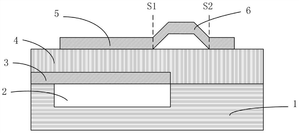
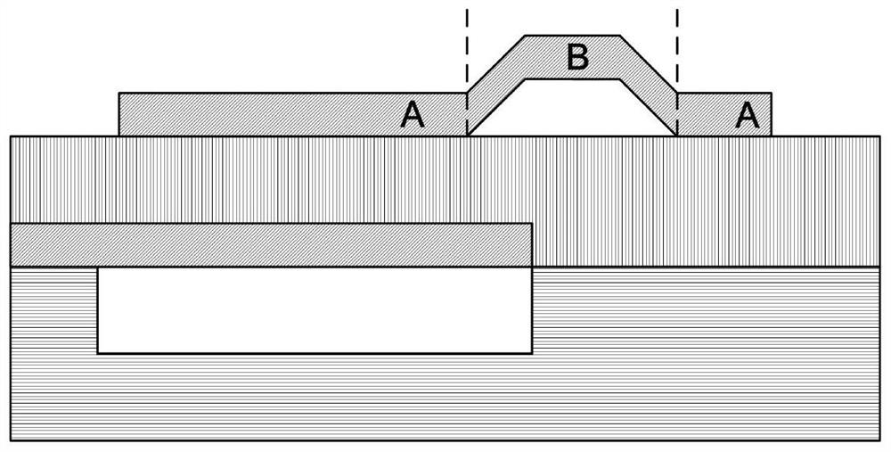
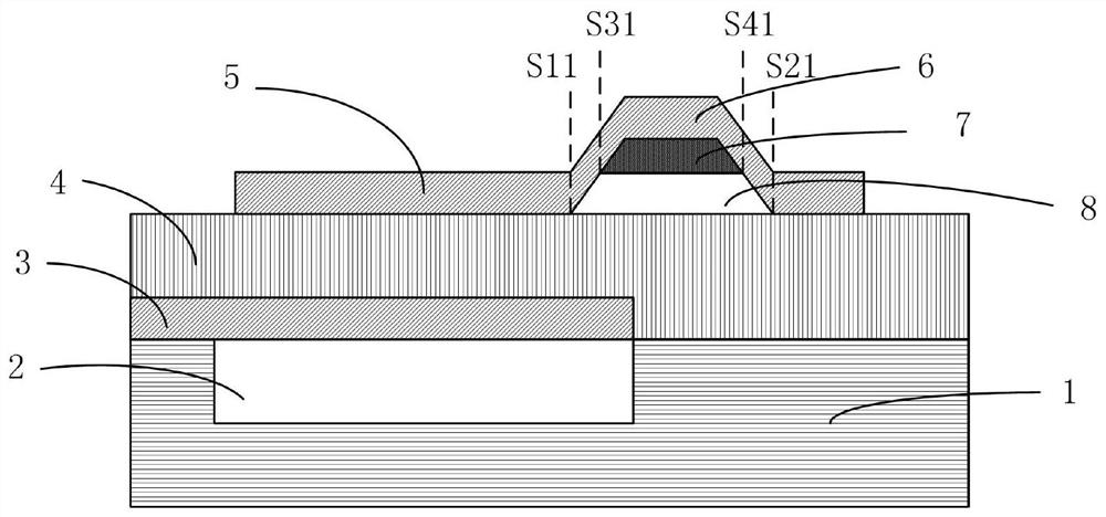
[0037] Example 1. combine Figure 2A and Figure 2B , the basic structure of a thin film bulk acoustic resonator with a high quality factor proposed by the present invention includes a substrate 1 with a groove 2 on the upper surface, a bottom electrode layer 3 above the substrate 1, a piezoelectric layer 4, a strip There is a top electrode layer 5 with an air bridge structure 6, wherein the air bridge structure 6 is provided with an acoustic rebound structure 7 that can rebound the transverse sound wave and improve the quality factor of the film bulk acoustic resonator; The boundary in one direction of the structure 6 is located inside the groove 2, and the boundary in the other direction extends beyond the boundary of the groove 2; the acoustic rebound structure 7 is in close contact with the air bridge structure 6, forming an acoustic wave in the horizontal propagation direction. Impedance mismatch interface; the material of the acoustic rebound structure 7 is a thin film...

Embodiment 2

[0038] Example 2. combine Figure 3A and Figure 3B , a preferred structure of a film bulk acoustic resonator with a high quality factor proposed by the present invention (Scheme 1). The preferred structure (Scheme 1) includes a substrate 1 with a groove 2 on the upper surface, a bottom electrode layer 3 above the substrate 1, a piezoelectric layer 4, and a top electrode layer 5 with a special-shaped air bridge structure 12. , the special-shaped air bridge structure 12 is provided with an acoustic rebound structure 7 that can rebound the transverse sound wave and improve the quality factor of the film bulk acoustic resonator; the boundary of one direction of the special-shaped air bridge structure 12 is located at the Inside the groove 2, the boundary in another direction extends beyond the boundary of the groove 2; the acoustic rebound structure 7 is in close contact with the special-shaped air bridge structure 12, forming an acoustic impedance mismatch interface in the hor...

Embodiment 3

[0039] Example 3. combine Figure 4A and Figure 4B , a preferred structure of a thin-film bulk acoustic resonator with a high quality factor proposed by the present invention (Scheme 2). The preferred structure (scheme 2) includes a substrate 1 with a groove 2 on the upper surface, a bottom electrode layer 3 above the substrate 1, a piezoelectric layer 4, and a top electrode layer 5 with an air bridge structure 6, the The air bridge structure 6 is provided with an acoustic rebound structure 7 that can rebound the transverse sound wave and improve the quality factor of the film bulk acoustic resonator; the boundary of one direction of the air bridge structure 6 is located within the groove 2 , the boundary in the other direction extends beyond the boundary of the groove 2; the acoustic rebound structure 7 is in close contact with the air bridge structure 6, forming an acoustic impedance mismatch interface in the horizontal propagation direction; the material of the acoustic ...


PUM


Abstract

The invention relates to a preferred structure of a high quality factor thin film bulk acoustic resonator, comprising a substrate with a groove on the upper surface, a bottom electrode layer above the substrate, and a piezoelectric layer, and is characterized in that it also includes a The top electrode layer of the special-shaped air bridge structure, which is equipped with an acoustic rebound structure that can rebound the transverse sound wave; the acoustic rebound structure is a convex or opposite bridge cavity of the special-shaped air bridge structure. The trapezoidal polyhedron is arranged horizontally in the area above the bridge cavity of the special-shaped air bridge structure. The top surface of the acoustic rebound structure is embedded and closely attached to the groove on the top surface of the bridge cavity of the special-shaped air bridge structure. The acoustic rebound structure There is an air gap between the bottom end surface and the suspension structure in the area below the bridge cavity of the special-shaped air bridge structure. The left and right sides of the acoustic rebound structure are respectively embedded and adjacent to the bridge cavity support structure of the special-shaped air bridge structure. The grooves on the inner side fit snugly. The invention can significantly improve the quality factor of the film bulk acoustic wave resonator.

Description

technical field [0001] The invention relates to a thin film bulk acoustic wave device, in particular to a preferred structure of a high quality factor thin film bulk acoustic wave resonator. Background technique [0002] With the development of wireless communication technology and smart phones, the RF front-end has higher and higher requirements on the performance indicators and integration of components. RF front-end filters, duplexers, and multiplexers based on thin film bulk acoustic wave devices have been widely used in smartphones, communication terminals, and In the communication base station, it will be applied in the communication equipment of the Internet of Vehicles, industrial control and other Internet of Things terminals in the future. In addition, oscillators based on thin film bulk acoustic wave devices are of great application value in high-speed serial data devices such as SATA hard drives, USB3.0 standard PC peripherals, C-type interfaces, and optical tra...

Claims


Application Information

Patent Timeline
Patent Type & Authority Patents(China)
IPC IPC(8): H03H9/17H03H9/02H03H9/13
CPCH03H9/02H03H9/02086H03H9/131H03H9/173H03H9/174H03H2009/02173
Inventor 赵洪元朱健
Owner NO 55 INST CHINA ELECTRONIC SCI & TECHNOLOGYGROUP CO LTD
Why Eureka
Try Eureka