Heating plate with controllable resistance in length direction and preparation process of heating plate

A preparation process and heating plate technology, applied in the direction of ohmic resistance heating, electric heating devices, electrical components, etc., can solve the difficult problems of continuous change of resistivity and high production cost, and achieve easy use and promotion, low production cost and simple preparation process Effect

Pending Publication Date: 2020-04-21
华智算(广州)科技有限公司
View PDF0 Cites 4 Cited by
  • Summary
  • Abstract
  • Description
  • Claims
  • Application Information

AI Technical Summary

Problems solved by technology

However, its production cost is high, and it is difficult to achieve continuous change in resistivity

Method used


Image

  • Heating plate with controllable resistance in length direction and preparation process of heating plate
  • Heating plate with controllable resistance in length direction and preparation process of heating plate
  • Heating plate with controllable resistance in length direction and preparation process of heating plate

Examples


Embodiment 1

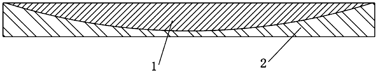
[0036] Such as figure 1 As shown, the heating plate with controllable resistance along the length direction provided by this embodiment is composed of an upper heating layer 1 and a lower heating layer 2. The lower surface of the upper heating layer 1 protrudes downward to form a convex curved surface, and the lower heating layer 2 The top surface of is concaved downwards to form a concave surface that fits the convex surface.

[0037] This embodiment also provides a preparation process for a heating plate with controllable resistance along the length direction, including the following steps:

[0038] (1) Calculate the resistance value range and resistance parameter range to be controlled according to the fuel plate of the simulation object, and select the materials of the upper heating layer 1 and the lower heating layer 2; for example, the material of the upper heating layer 1 is 321 stainless steel ; The material of the lower heating layer 2 is an alloy with the grade of I...

Embodiment 2

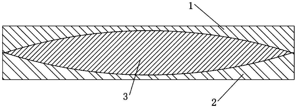
[0045] Such as image 3As shown, the heating plate with controllable resistance along the length direction provided by this embodiment is formed by stacking the upper heating layer 1, the middle heating layer 3 and the lower heating layer 2 sequentially from top to bottom, and the lower surface of the upper heating layer 1 is sunken upwards. A concave curved surface is formed, the upper surface of the lower heating layer 2 is depressed downward to form a concave curved surface, the concave curved surface of the upper heating layer 1 and the concave curved surface of the lower heating layer 2 form a cavity, the middle heating layer 3 is accommodated in the cavity, and the middle heating The thickness of layer 3 gradually decreases from the center to the edge.

[0046] In this embodiment, the materials of the upper heat generating layer 1 , the middle heat generating layer 3 and the lower heat generating layer 2 are different.

[0047] This embodiment also provides a preparatio...


PUM


Abstract

The invention discloses a heating plate with controllable resistance in a length direction and a preparation process of the heating plate. The heating plate with controllable resistance in the lengthdirection comprises at least two heating layers; the thickness of each heating layer continuously changes in a gradient manner along the length direction; the change of the thickness of one heating layer in two adjacent heating layers along the length direction is opposite to the change of the thickness of the other heating layer in the length direction; a connecting contact surface between the two adjacent heating layers is a curved surface; and the two adjacent heating layers are made of different materials. According to the a heating plate and the preparation process thereof the invention,the heating plates are formed by stacking a plurality of heating layers made of different materials; the resistance of the heating plate is accurately controlled to continuously change along the length direction by designing the thickness of the heating layers to continuously change along the length direction in a gradient manner, so that the metal plate with controllable resistance along the length direction provided by the invention can be applied to a fuel plate heating simulation test.

Description

technical field [0001] The invention relates to the technical field of thermal energy engineering, in particular to a heating plate with controllable resistance along the length direction and a preparation process thereof. Background technique [0002] In a nuclear reactor, there are a large number of fuel rods or plates whose heat generation is not uniform along the length direction (axial direction). In the design process, it is necessary to carry out relevant experiments to study the relevant properties of the fuel. Generally, electric heating is used in experiments to simulate the nuclear heat release of fuel, which requires that the heating rate of the heating layer used in the experiment is controllable along the length direction, that is, Its resistance along the length direction can be precisely controlled as required. [0003] The method that can be investigated at present to satisfy the above functions is to use gradient functional materials, which are a new type ...

Claims


Application Information

Patent Timeline
IPC IPC(8): H05B3/22H05B3/10H05B3/12
CPCH05B3/22H05B3/10H05B3/12
Inventor 巫军
Owner 华智算(广州)科技有限公司
Why Eureka
Try Eureka