
Oil-electricity hybrid multifunctional unmanned aerial vehicle

An unmanned aerial vehicle and a multi-functional technology, applied in the field of unmanned aerial vehicles, can solve the problems of poor protection effect and simple structure, and achieve the effect of strong practicability, good protection effect and improved buffer performance.

Pending Publication Date: 2020-04-24
北京致媒科技有限公司
View PDF0 Cites 0 Cited by
  • Summary
  • Abstract
  • Description
  • Claims
  • Application Information

AI Technical Summary

Problems solved by technology

[0003] Most of the current drones land hard. Although the drone can fly straight up and down, it still has a certain impact when landing. Some drones with buffer protection have a simple structure and are simply buffered by setting a spring connection. , the protection effect is poor and needs to be optimized

Method used


Image

  • Oil-electricity hybrid multifunctional unmanned aerial vehicle
  • Oil-electricity hybrid multifunctional unmanned aerial vehicle
  • Oil-electricity hybrid multifunctional unmanned aerial vehicle

Examples


Embodiment 1

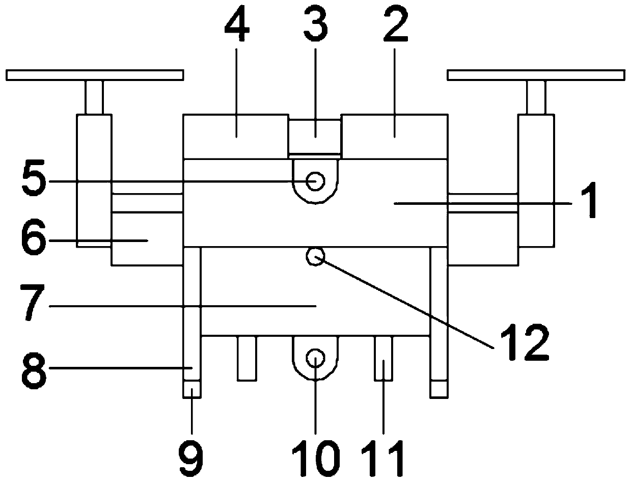
[0021] Such as Figure 1-4 The oil-electric hybrid multi-functional unmanned aerial vehicle shown includes an unmanned aerial vehicle body 1, an engine 2 and a generator 4 are fixedly installed on the upper end of the unmanned aerial vehicle main body 1, and the generator 4 is connected to the engine 2 through a coupling 3. Connected, that is, using the existing unmanned aerial vehicle that can fly normally as the body, through the generator 4 and the engine 2, the kinetic energy of the engine 2 is converted into the electrical energy of the generator 4, and then the drone body 1 is powered, which greatly improves The endurance of the unmanned aerial vehicle, thereby improving its practicality; The first camera 5 and the floating plate 6 are fixedly installed on the side of the unmanned aerial vehicle body 1, and the first camera 5 is used for aerial photography during flight, and the setting of the floating plate 6 can be Make the UAV stay on the water surface for shooting, t...

Embodiment 2

[0025] This embodiment is further optimized on the basis of Embodiment 1. A water tank 7 is fixedly installed at the bottom of the drone body 1. A water inlet 12 is provided at the upper end of the side of the water tank 7. A nozzle is fixedly installed at the bottom of the water tank 7. 11. By setting the water tank 7, water can be taken while shooting on the water surface, which is convenient to realize simple water source collection or higher irrigation work, and further improves the practicability.

[0026] Further, a second camera 10 is fixedly installed on the bottom of the water tank 7. Preferably, the second camera 10 is an underwater camera, which is convenient for shooting underwater while shooting on the water surface, and has strong practicability.


PUM


Abstract

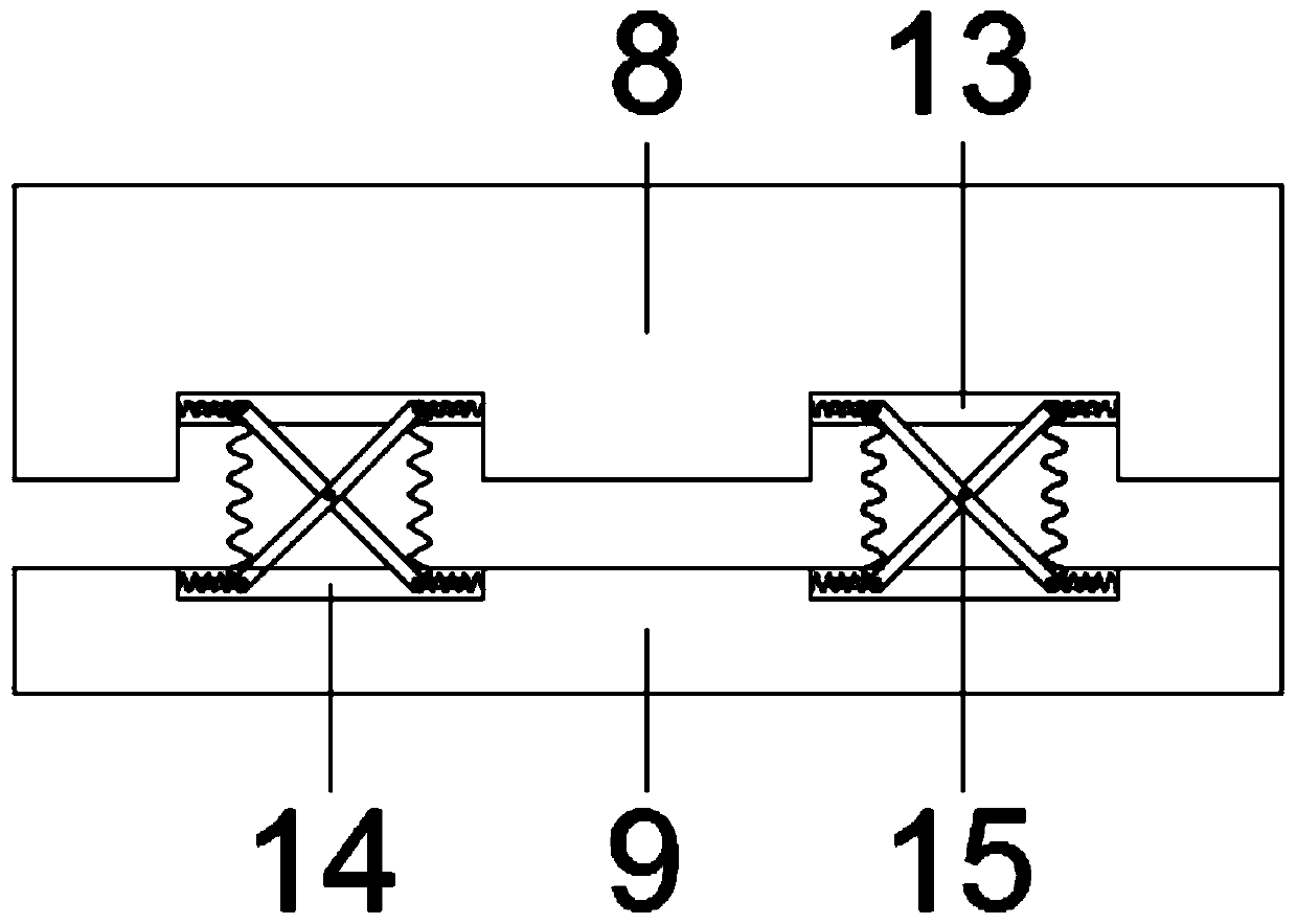
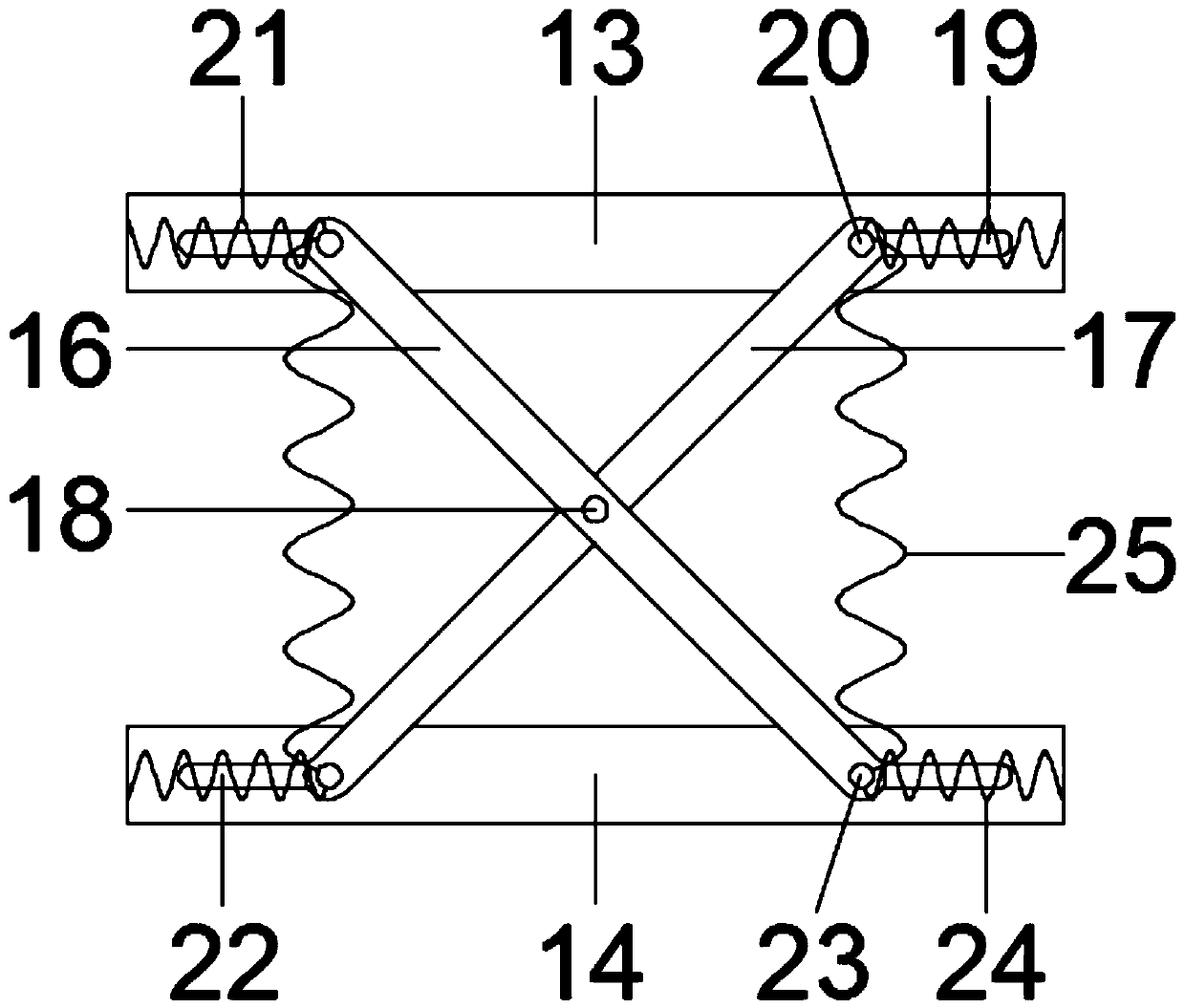
The invention relates to an oil-electricity hybrid multifunctional unmanned aerial vehicle, and belongs to the technical field of unmanned aerial vehicles. The vehicle comprises an unmanned aerial vehicle body, an engine and a generator are fixedly mounted at the upper end of the unmanned aerial vehicle body; the generator is connected with the engine through a coupler, a first camera and a floating plate are fixedly installed on the side face of the unmanned aerial vehicle body, supporting legs are fixedly installed at the bottom of the unmanned aerial vehicle body, damping bases are installed at the bottoms of the supporting legs, and the damping bases are connected with the supporting legs through damping mechanisms. By arranging the damping mechanism, the buffering performance of the unmanned aerial vehicle during landing is greatly improved, the protection effect is good, meanwhile, the water tank and the underwater camera are arranged to be matched with the floating plate, underwater and water surface shooting can be conducted through the unmanned aerial vehicle, the effects of water source collection and higher irrigation can be achieved, the functions are rich, and the practicability is high.

Description

technical field [0001] The invention relates to the technical field of unmanned aerial vehicles, in particular to an oil-electric hybrid multifunctional unmanned aerial vehicle. Background technique [0002] Unmanned aircraft, referred to as "unmanned aerial vehicle", or "UAV" in English, is an unmanned aircraft that is controlled by radio remote control equipment and its own program control device, or is completely or intermittently operated autonomously by an on-board computer. With the improvement of technology and the reduction of cost, the application range of drones has been improved. Drones + industry applications are the real needs of drones; Applications in rescue, wildlife observation, infectious disease monitoring, surveying and mapping, news reporting, power inspection, disaster relief, film and television shooting, romance creation, etc. [0003] Most of the current drones land hard. Although the drone can fly straight up and down, it still has a certain impact...

Claims


Application Information

Patent Timeline
IPC IPC(8): B64C39/02B64D27/02B64C25/62B64D47/08B64D1/18
CPCB64C39/02B64D27/02B64C25/62B64D47/08B64D1/18B64U50/11B64U50/19B64D27/026
Inventor 上官铭铭焦东升肖劲锋
Owner 北京致媒科技有限公司
Learn More