
Automatic programming device for chips

A technology of chips and drive parts, which is applied in the direction of conveyor control devices, transportation and packaging, and conveyor objects, can solve problems such as low work efficiency, space occupation, and waste of resources, and achieve waste of materials, and solve the problem of taking up a lot of space. The effect of improving flexibility

Active Publication Date: 2020-04-24
深圳市之诺微电子有限公司
View PDF7 Cites 0 Cited by
  • Summary
  • Abstract
  • Description
  • Claims
  • Application Information

AI Technical Summary

Problems solved by technology

[0003] Existingly, for this kind of programming, the PCB board is conveyed by the conveyor belt, and the programming is performed according to the preset sets of fixed types of programming needles after the machine detects, which leads to the need for different programming points for different types of chips. The needle recording model corresponds to it, which not only takes up a lot of space and causes a waste of resources, but also needs to manually confirm the type to be burned and install the corresponding template when using it, which is inefficient; therefore, a high flexibility and small size is required. chip automatic programming device

Method used


Image

  • Automatic programming device for chips
  • Automatic programming device for chips
  • Automatic programming device for chips

Examples


Embodiment

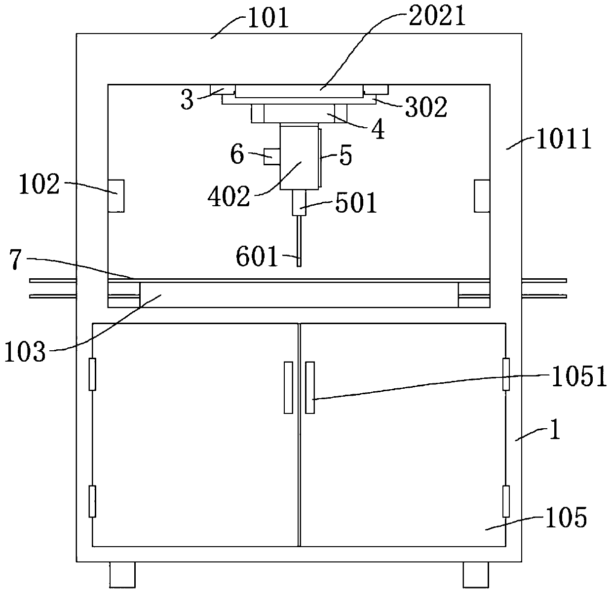
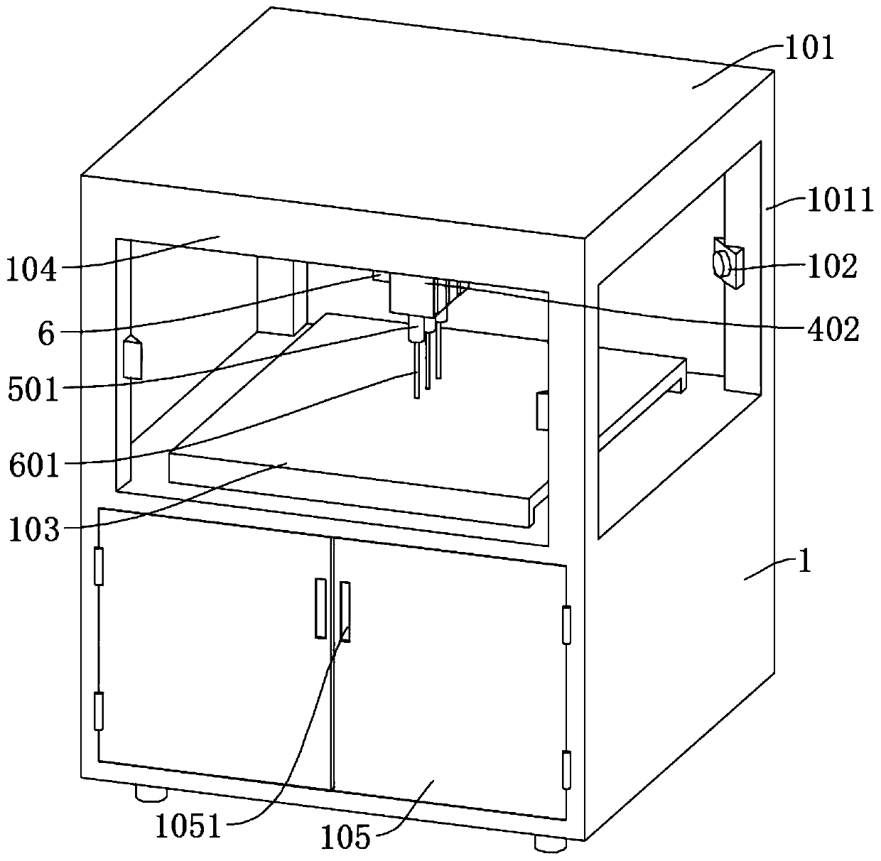
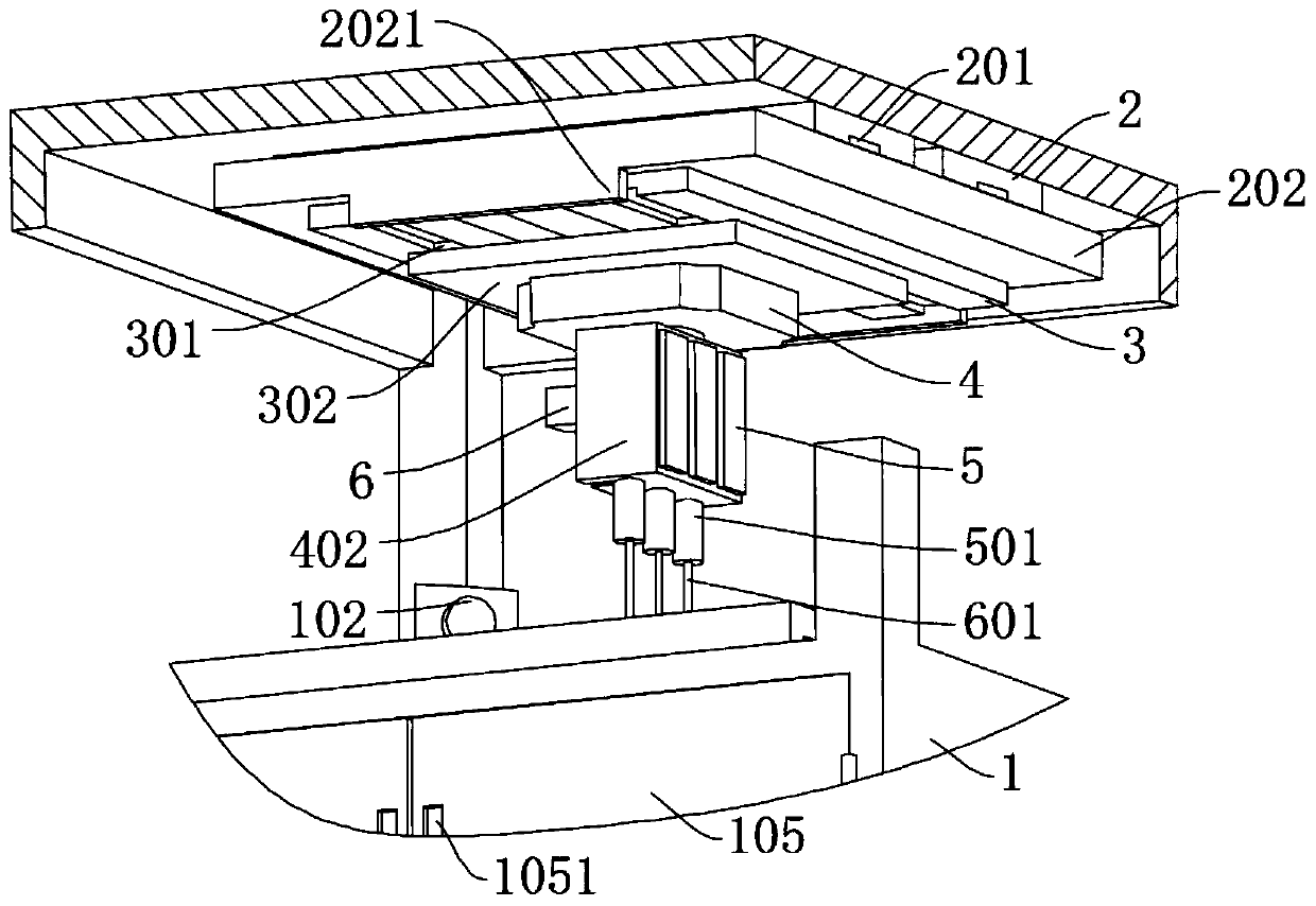
[0026] refer to Figure 1-4 , an automatic chip programming device, including a position sensor 102, a heater 6, a conveyor belt 7, an installation box 1, the top of the installation box 1 is connected to a first workbench 101 through a connecting rod 1011, and the position sensor 102 is connected to the connecting rod 1011, the bottom of the first workbench 101 is slidably connected with the second workbench 202, the bottom of the first workbench 101 is fixedly connected with a transverse driving part for driving the second workbench 202 to move, and the bottom of the second workbench 202 is slidably connected with the second workbench 202. Three workbenches 302, the bottom of the second workbench 202 is fixedly connected with a longitudinal driving part for driving the movement of the third workbench 302, the bottom of the third workbench 302 is rotatably connected with a fourth workbench 402, and the bottom of the third workbench 302 is fixedly connected There is a first dr...


PUM


Abstract

The invention discloses an automatic programming device for chips, and belongs to the technical field of chip manufacturing. The automatic programming device for the chips includes a position sensor,a heater, a conveyor belt and an installation box; and the installation box is connected to a first working table, a second working table is slidingly connected to the bottom of the first working table, a horizontal driving part for driving the second working table to move is connected to the bottom of the first working table, a third working table is slidingly connected to the bottom of the second working table, a longitudinal driving part for driving the third working table to move is connected to the bottom of the second working table, a fourth working table is rotatably connected to the bottom of the third working table, a first driving part for driving the fourth working table to rotate is fixedly connected to the bottom of the third working table, telescopic rods are slidingly connected to the interior of the fourth working table, each programming pin is connected to the bottom of one corresponding telescopic rod, a second driving part is connected to the side wall of the fourthworking table, and the conveyor belt is slidingly connected to the supporting table. The device effectively solves traditional template consumables, and has high flexibility and universality.

Description

technical field [0001] The invention relates to the technical field of chip manufacturing, in particular to an automatic chip programming device. Background technique [0002] At present, all walks of life are using chips. Many substitute chips need to be replaced after their service life is reached. However, each chip must be powered on and burned before being soldered to the PCB board, and the relevant programs are burned to the chip. In the MCU in. [0003] Currently, for this kind of programming, the PCB board is conveyed by the conveyor belt. After being detected by the machine, the programming is performed according to the preset sets of fixed types of programming pins, which leads to the need for different programming points for different types of chips. The needle recording model corresponds to it, which not only takes up a lot of space and causes a waste of resources, but also needs to manually confirm the type to be burned and install the corresponding template wh...

Claims


Application Information

Patent Timeline
IPC IPC(8): B65G49/06B65G43/08G06F8/61
CPCB65G43/08B65G49/06B65G2203/042G06F8/63
Inventor 周露露李立
Owner 深圳市之诺微电子有限公司
Learn More