Composite speed reducer
A technology of reducer and body, applied in mechanical equipment, transmission parts, gear transmission and other directions, can solve the problem of inability to meet the performance requirements of mechanical equipment, and achieve the effect of compact structure, strong overload capacity and low noise
- Summary
- Abstract
- Description
- Claims
- Application Information
AI Technical Summary
Problems solved by technology
Method used
Image

Examples
Embodiment Construction
[0013] Further description will be made below in conjunction with drawings and embodiments.
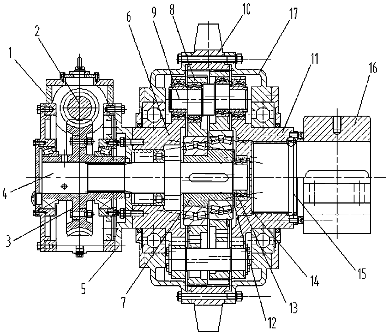
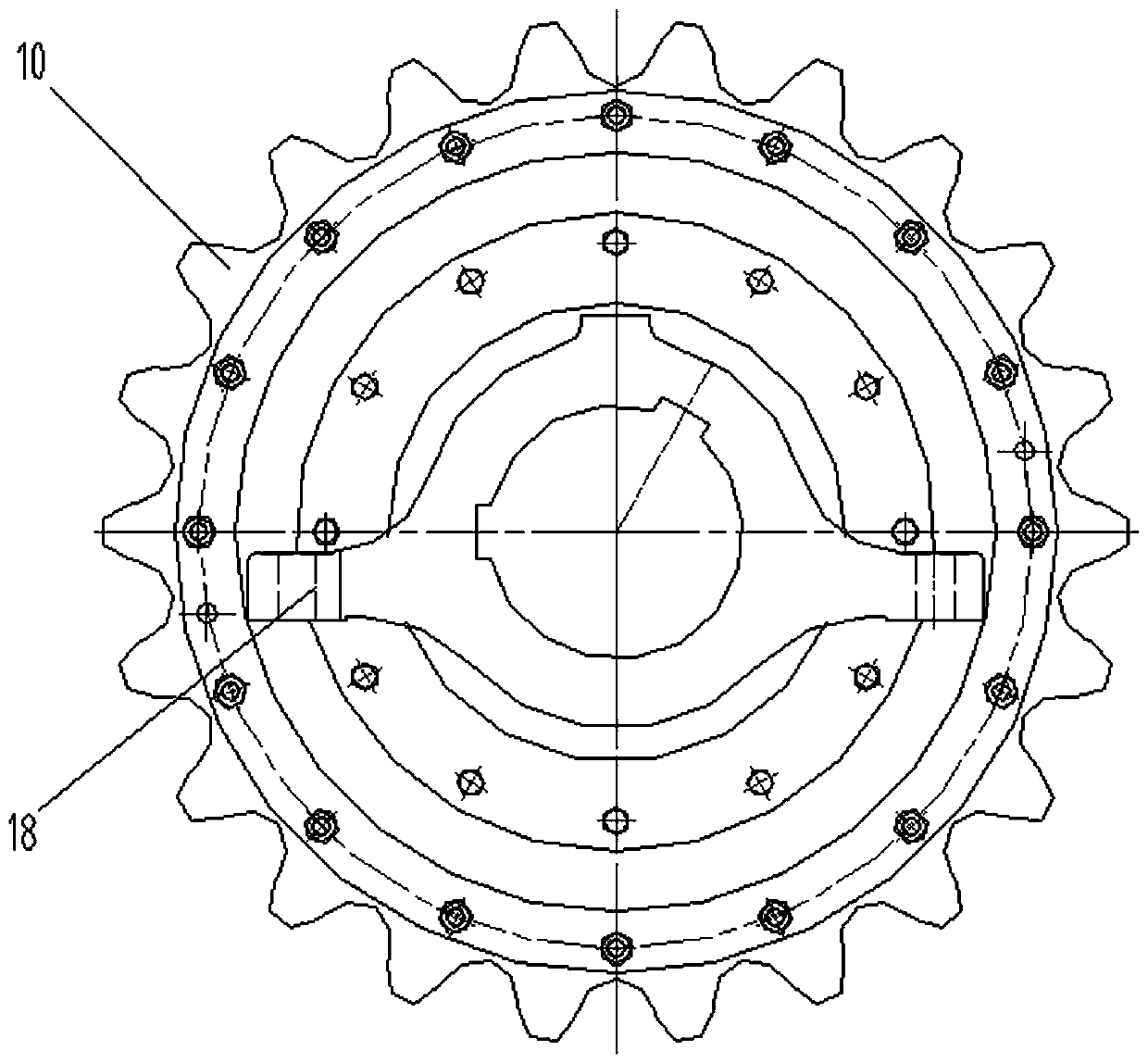
[0014] figure 1 , 2 As shown: a compound reducer includes a box body 1, a worm 2, a worm wheel 3, a spline input shaft 4, a connection plate 5, a front support plate 6, an eccentric sleeve 7, a planetary gear 8, an eccentric shaft 9, an internal gear 10, Rear support plate 11, spacer ring 12, double row roller bearing 13, positioning ring plate 14, thread plug cap 15, bearing 16, body 17, foot seat 18. The worm 2 and the worm wheel 3 are arranged in the box body 1, and one end of the spline input shaft 4 is threaded on the worm wheel 3; the box body 1 is locked and connected to the front support plate 6 through the connection plate 5, and the front and rear support plates 6, 11 are connected through The support shaft is passed through, the other end of the spline input shaft 4 is connected to the front and rear support plates through the bearing, and the other end of the spline inpu...
PUM
 Abstract
Description
Claims
Application Information