Strain-controlled thermal mechanical fatigue performance test method

A technology of thermomechanical fatigue and testing methods, applied in the direction of applying stable tension/pressure to test the strength of materials, etc., can solve problems such as large deviations in mechanical deformation, achieve scientific and reasonable test results, and reduce the risk of breaking or bending The effect of probability

Active Publication Date: 2020-04-24
HEFEI GENERAL MACHINERY RES INST
View PDF11 Cites 3 Cited by
  • Summary
  • Abstract
  • Description
  • Claims
  • Application Information

AI Technical Summary

Problems solved by technology

When the temperature fluctuates greatly at a certain moment, especially during the cooling process, the existin...

Method used


Image

  • Strain-controlled thermal mechanical fatigue performance test method
  • Strain-controlled thermal mechanical fatigue performance test method
  • Strain-controlled thermal mechanical fatigue performance test method

Examples


Embodiment Construction

[0045] Below in conjunction with embodiment technical solution of the present invention is made more specific description:

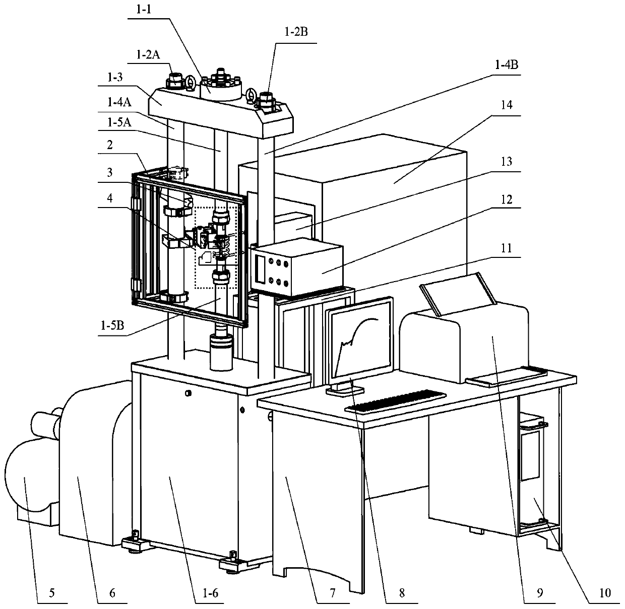
[0046] For the Cr-Mo steel material whose grade is SA387Gr11Cl2, adopt such as figure 1 The thermomechanical fatigue test system shown in the figure carries out the thermomechanical fatigue test in the same phase, the thermal cycle range is 80°C to 490°C, the mechanical strain cycle range is -0.8% to +0.8%, the test period is 410s, and the heating and cooling rate is 2°C / s , the mechanical deformation rate is 1.905um / s.

[0047] The thermomechanical fatigue testing system adopted in the present invention includes a fatigue loading subsystem, a fatigue sample, a heating subsystem, a temperature control subsystem, a strain measurement subsystem, a cooling subsystem and a computer control subsystem.

[0048] The fatigue loading subsystem applies the required tensile-compression zero-crossing mechanical load to the fatigue sample stably held by the high-tem...


PUM


Abstract

The invention relates to a strain-controlled thermal mechanical fatigue performance test method. The method comprises the following steps: firstly, carrying out testing to obtain thermal deformation data in a pure thermal cycle period; dividing the thermal cycle period into four parts, a temperature range of the I part being T0-Tmax, a temperature range of the II part being Tmax-T0, a temperaturerange of the III part being T0-Tmin, and a temperature range of the IV part being Tmin-T0; carrying out segmenting at the moment positions at which the thermal deformation rates change in the parts I,II, III and IV, and then, respectively solving the thermal deformation rate vth of each segment through linear fitting; calculating and determining the total deformation rate vtot of each segment according to the equation vtot=vm+vth, wherein the vm is the mechanical deformation rate required by the test; and finally, controlling a thermo-mechanical fatigue test system to apply a constant mechanical deformation rate vm to the test sample according to the total deformation rate vtot of each segmented test sample. According to the method, the probability that the sample is snapped or bent in advance is reduced, and the fatigue characteristic of the sample under the combined action of temperature and mechanical load at different phase angles can be reflected more accurately.

Description

technical field [0001] The invention belongs to the field of material performance testing, and in particular relates to a strain-controlled thermomechanical fatigue performance testing method. Background technique [0002] The development of modern science and technology tends to require higher and higher service temperatures for engineering components, which has brought the severity of transient heating during work to many equipment in industries such as metallurgy, aviation and chemical industry, especially during startup- During stop or acceleration / deceleration. Various transient thermal stresses and mechanical stresses caused by rapid heating or cooling are superimposed together to form a serious compound stress cycle. Once the equipment fails under the thermal engine fatigue load for a long time, it will often be accompanied by catastrophic accidents such as fire, poisoning, and environmental pollution. . In order to optimize the material selection design and accurat...

Claims


Application Information

Patent Timeline
IPC IPC(8): G01N3/18
CPCG01N3/18
Inventor 鲁志兵陈学东范志超董杰
Owner HEFEI GENERAL MACHINERY RES INST
Why Eureka
Try Eureka