Planar diaphragm loudspeaker with asynchronous magnetic reflux structure

A technology of planar diaphragm and loudspeaker, applied in the field of loudspeaker, can solve problems such as difficulty in effective reduction, low production capacity and manufacturing efficiency, and poor economy, so as to reduce complex manufacturing process, improve dynamic control ability, and reduce manufacturing cost Effect

Inactive Publication Date: 2020-04-24
杭州比值科技有限公司
View PDF5 Cites 0 Cited by
  • Summary
  • Abstract
  • Description
  • Claims
  • Application Information

AI Technical Summary

Problems solved by technology

Its advantages are: relatively easy to make, good linearity, small distortion, and wide frequency response; the disadvantage is: because the sounding diaphragm of the moving coil unit in the earphone is a cone-shaped structure, and when the power exceeds 60% during the sounding process, Due to the inherent limitations of the diaphragm shape and material, there is obvious distortion and the closer to the full load power, the distortion will increase exponentially, which will seriously deteriorate the sound
Its advantages are: long service life and high efficiency; disadvantages are: high price, large distortion, harsh high frequency, narrow frequency response, complex production process, high defect rate, often used in early telephone handsets
Due to the thinness of the diaphragm, the sound quality of electrostatic earphones is naturally light and transparent, and the performance of low frequency, sound thickness and density is slightly inferior; the disadvantage is that electrostatic earphones are mostly hand-made with a high defect rate and it is difficult to effectively reduce them. Production capacity and manufacturing efficiency are extremely low during manufacturing, and it is difficult to commercialize on a large scale, which is an insurmountable threshold
[0006] However, when the working power of the moving coil resolution exceeds 60%, the resolution begins to decline, and the sound is chaotic, and the greater the load, the more serious it is; the traditional dynamic speaker has been developed to the limit by the industry, and it is difficult to innovate with the acoustic logic such as physical structure. Upgrading; the acoustic characteristics of traditional dynamic speakers are difficult to upgrade with high quality in the original structure, and the cost for every improvement in sound quality will be several times or even more times, and the economy is very poor; the traditional dynamic speakers It is difficult for the diaphragm to be nano-scale thick, and it is difficult to greatly improve the sound quality. The sound with higher resolution has reached the limit.
In the actual manufacturing process of the planar diaphragm speaker structure, it is difficult to make the volume very small. Most of them are the volume of headphones, and it is impossible to achieve the in-ear earplug structure.

Method used


Image

  • Planar diaphragm loudspeaker with asynchronous magnetic reflux structure
  • Planar diaphragm loudspeaker with asynchronous magnetic reflux structure
  • Planar diaphragm loudspeaker with asynchronous magnetic reflux structure

Examples


Embodiment 1

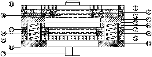
[0078] The numbers of the upper magnets and the lower magnets are different, and a plurality of upper magnets and a plurality of lower magnets are alternately arranged.

[0079] Such as Figure 1 to Figure 3 , Figure 7 As shown, the symmetrical magnetic circuit structure: the upper magnet and the lower magnet have equal length, equal width and equal height; multiple gaps are formed between adjacent upper magnets, and the lower magnet is arranged facing the gap.

Embodiment 2

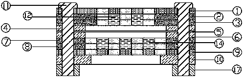
[0081] The numbers of the upper magnets and the lower magnets are different, and a plurality of upper magnets and a plurality of lower magnets are alternately arranged.

[0082] Symmetrical magnetic circuit structure: the length, width, and height of the upper magnet and the lower magnet are equal; when the number of upper magnets is greater than that of the lower magnets, multiple gaps are formed between adjacent upper magnets, and the lower magnets face the gaps Setting, the relative position of the excess gap formed between the remaining upper magnets is not provided with the lower magnets, and is relatively empty.

Embodiment 3

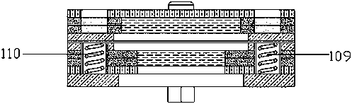
[0084] The numbers of the upper magnets and the lower magnets are different, and a plurality of upper magnets and a plurality of lower magnets are alternately arranged.

[0085] Symmetrical magnetic circuit structure: the length, width, and height of the upper and lower magnets are equal; when the number of upper and lower magnets is greater than the number of upper magnets, multiple gaps are formed between adjacent lower magnets, and the upper magnet is facing the gap Setting, the relative position of the excess gap formed between the remaining lower magnets is not provided with lower magnets, and is relatively empty.


PUM


Abstract

The invention provides a planar diaphragm loudspeaker with an asynchronous magnetic reflux structure, which comprises at least one upper magnet support frame, at least one lower magnet support frame,at least one lower magnet support frame and at least one lower magnet support frame, a first supporting mechanism and a second supporting mechanism are arranged below the upper magnet set. A voice coil diaphragm mechanism is installed between the first support mechanism and the second support mechanism. At least one lower magnet support frame is further arranged below the second support mechanism;a lower magnet set is fixed to the inner side of the lower magnet supporting frame, a first conductive metal sheet and a second conductive metal sheet are arranged below the lower magnet set, the upper magnet set comprises a plurality of upper magnets, the lower magnet set comprises a plurality of lower magnets, the number of the upper magnets is different from that of the lower magnets, and theupper magnets and the lower magnets are arranged in a staggered mode. According to the planar diaphragm loudspeaker, the diameter, the size and the weight of a planar diaphragm loudspeaker body structure can be effectively reduced, the sounding quality is remarkably improved, the overall structure of the loudspeaker is optimized, and the size miniaturization is realized.

Description

technical field [0001] The invention relates to the technical field of loudspeakers, in particular to a planar diaphragm loudspeaker with an asynchronous magnetic return structure. Background technique [0002] Currently commonly used earphones are mainly divided into dynamic earphones, moving iron earphones and electrostatic (capacitive) earphones according to their different sounding principles. [0003] Dynamic earphones are the most common form of earphones today. It fixes the coil on the diaphragm and places it in a fixed magnetic field generated by a permanent magnet. The signal passes through the coil to cut the magnetic field lines, thereby driving the diaphragm to vibrate and produce sound together. Its advantages are: relatively easy to make, good linearity, small distortion, and wide frequency response; the disadvantage is: because the sounding diaphragm of the moving coil unit in the earphone is a cone-shaped structure, and when the power exceeds 60% during the s...

Claims


Application Information

Patent Timeline
IPC IPC(8): H04R7/04H04R9/02H04R9/04H04R9/06
CPCH04R7/04H04R9/02H04R9/025H04R9/04H04R9/06H04R2209/024
Inventor 王洪岩王洪宇韩越王楠
Owner 杭州比值科技有限公司
Why Eureka
Try Eureka