Uniform mixing equipment for biomass processing

A biomass and mixing technology, which is applied in the direction of mixers, chemical/physical processes, mixers with rotating containers, etc., can solve the problems of long time and slow mixing speed, and achieve high work efficiency and fast mixing speed , full effect of mixing

Inactive Publication Date: 2020-04-28
沈桂香
View PDF0 Cites 5 Cited by
  • Summary
  • Abstract
  • Description
  • Claims
  • Application Information

AI Technical Summary

Problems solved by technology

[0003] In the process of biomass processing, it is necessary to mix various raw materials. The existing mixing device generally adopts the rotation of the stirring shaft and the stirring rod installed at a fixed position for stirring. This kind of stirring prevents the mixing speed from being slow and time-consuming longer

Method used


Image

  • Uniform mixing equipment for biomass processing
  • Uniform mixing equipment for biomass processing
  • Uniform mixing equipment for biomass processing

Examples


Embodiment 1

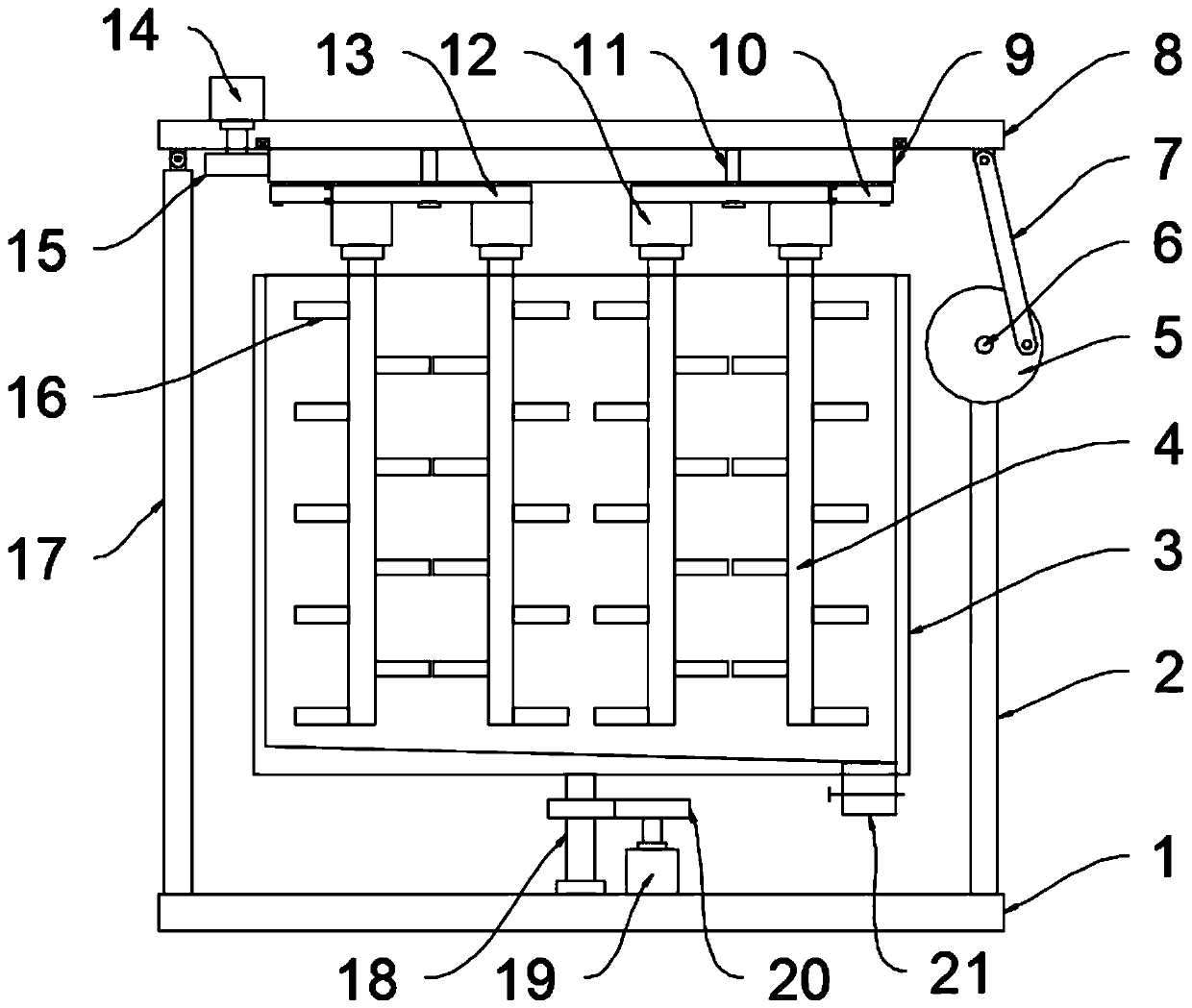
[0027] see Figure 1~3 , in an embodiment of the present invention, a kind of mixing equipment for biomass processing, comprising a bottom plate 1, a holding frame 3, a mounting plate 8 and a stirring unit, a holding frame 3 is installed above the bottom plate 1, the top of the holding frame 3 is open, and the holding One side of the bottom of the frame 3 is provided with a discharge port 21, and a valve is installed on the discharge port 21. In this embodiment, the bottom of the inner cavity of the containing frame 3 is inclined to the side close to the discharge port 21, which is convenient for discharging and dressing. A mounting plate 8 connected to the bottom plate 1 through a connecting mechanism is installed above the frame 3, and a stirring unit for stirring the biomass raw materials in the containing frame 3 is installed on the mounting plate 8. In this embodiment, the containing frame 3 is rotated and installed On the bottom plate 1, a mounting column 18 is fixed on ...

Embodiment 2

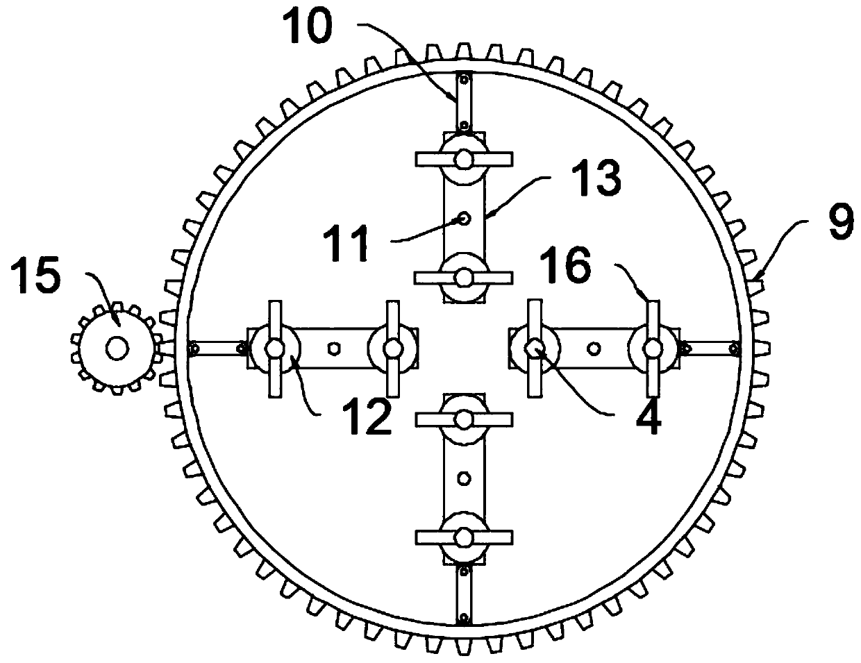
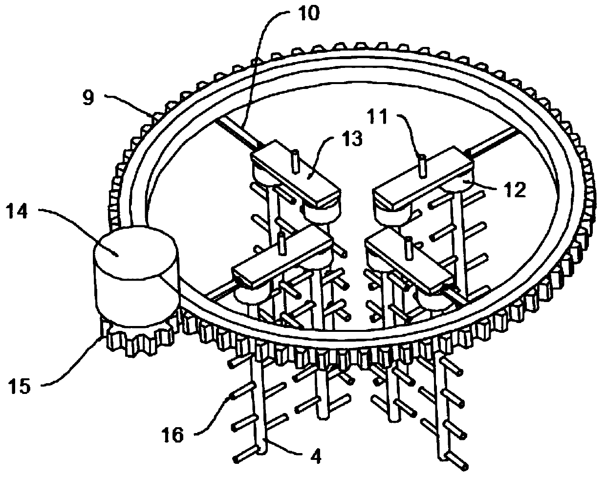
[0030] see Figure 4The difference between this embodiment of the present invention and Embodiment 1 is that, in order to ensure the stability of the container frame 3 when it rotates, a plurality of support legs 22 are fixed at the bottom of the container frame 3, and the support legs 22 are slidably connected to the upper part of the bottom plate 1, In this embodiment, the upper part of the bottom plate 1 is provided with an annular sliding groove for supporting the sliding of the legs 22 .

[0031] The working principle of the present invention is: when working, the biomass raw material is added from the top of the dress frame 3, and then the third motor 19 is started, and the third motor 19 drives the installation column 18 to rotate through the gear pair 20, and the installation column 18 drives the dress frame 3 to rotate, The containing frame 3 drives the biomass raw material inside to rotate, and cooperates with the stirring unit to fully stir and mix the biomass raw m...


PUM


Abstract

The invention discloses uniform mixing equipment for biomass processing. The uniform mixing equipment comprises a bottom plate, a containing frame, a mounting plate and stirring units, the containingframe is mounted above the bottom plate; a mounting plate connected with the bottom plate through a connecting mechanism is mounted above the containing frame; a stirring unit for stirring biomass rawmaterials in the containing frame is mounted on the mounting plate; the stirring unit comprises a plurality of groups of stirring assemblies and a driving assembly for driving the plurality of groupsof stirring assemblies to move; the driving assembly comprises a driving ring, a second connecting rod, a supporting plate, a pin shaft and a power mechanism for driving the driving ring to rotate positively and negatively; and the connecting mechanism comprises a first supporting rod, a second supporting rod and a moving assembly used for driving the mounting plate to move. The stirring unit isarranged, biomass raw materials in the containing frame can be fully and uniformly stirred in a large-range and movable mode, the uniform mixing speed is high, the connecting mechanism is arranged, the stirring angle of the stirring unit can be continuously changed, stirring is more sufficient and uniform, and the uniform mixing efficiency is further improved.

Description

technical field [0001] The invention relates to the technical field of biomass processing, in particular to a mixing device for biomass processing. Background technique [0002] Among all kinds of renewable energy, due to the potential ecological and environmental risks of nuclear energy and large-scale hydropower, and the constraints of regional resources such as wind energy and geothermal energy, vigorous development has been restricted and questioned, while biomass energy is characterized by ubiquity, abundance, Features such as reproducibility are recognized. The uniqueness of biomass lies not only in its ability to store solar energy, but also as a renewable carbon source that can be converted into conventional solid, liquid and gaseous fuels. Energy sources such as coal, oil, and natural gas are essentially transformed from biomass energy. of. [0003] In the process of biomass processing, it is necessary to mix various raw materials. The existing mixing device gener...

Claims


Application Information

Patent Timeline
Patent Type & Authority Applications(China)
IPC IPC(8): B01F9/12B01F9/10B01F15/00B01F29/83
CPCB01F29/80B01F29/83B01F33/86B01F35/325B01F35/31B01F35/30B01F35/3215B01F35/3204
Inventor 沈桂香童文连王松杰
Owner 沈桂香
Why Eureka
Try Eureka