Grinding device for art painting paint

A grinding device and painting technology, applied in application, cocoa, grain processing, etc., can solve the problem of long pigment grinding time, and achieve the effect of freely adjusting the speed of the grinding seat, large grinding area, and improving efficiency

Inactive Publication Date: 2021-04-13
CHONGQING TECH & BUSINESS UNIV
View PDF13 Cites 0 Cited by
  • Summary
  • Abstract
  • Description
  • Claims
  • Application Information

AI Technical Summary

Problems solved by technology

[0003] The object of the present invention is to provide a kind of grinding device for art painting paint, to solve the problem that the pigment grinding time is longer

Method used


Image

  • Grinding device for art painting paint
  • Grinding device for art painting paint
  • Grinding device for art painting paint

Examples


Embodiment 1

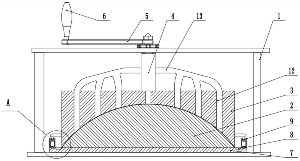
[0032] Basic as attached figure 1 with attached figure 2 Shown: a grinding device for art painting paint, including a bracket 1, on which a grinding seat 2 is welded and fixed. The center of the grinding seat 2 is an upward hemispherical protrusion. The bracket 1 is provided with a grinding cover 3 directly above the grinding seat 2, the bottom surface of the grinding cover 3 is a spherical concave surface sunken inward, and the concave surface completely covers the hemispherical protrusion. The center of the top surface of the grinding cover 3 is upwardly fixedly connected with a shaft 4, the shaft 4 is rotatably connected to the support 1, the top of the shaft 4 is threaded and fixedly connected with a sub-rod 5, and the free end of the sub-rod 5 is welded and fixed with a handle 6.

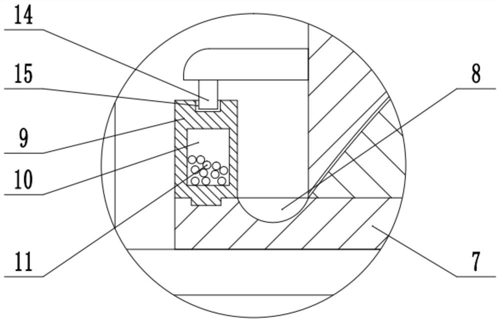
[0033] The bottom of the grinding seat 2 is provided with a base plate 7, and the base plate 7 and the grinding seat 2 are integrally formed. An annular groove 8 is formed on the top of the...

Embodiment 2

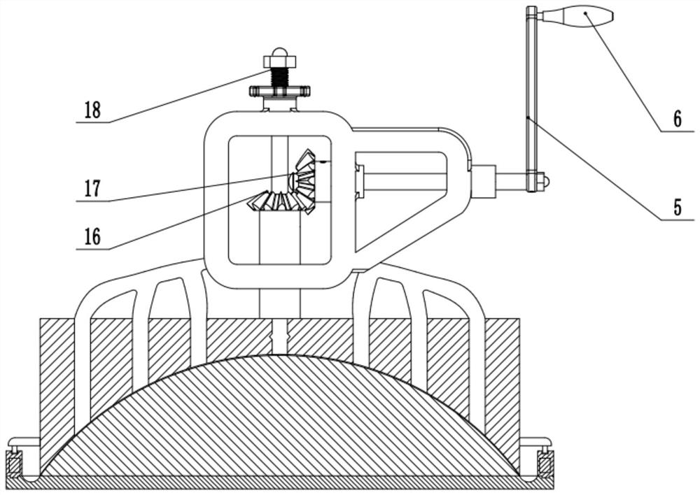
[0038] The difference between this embodiment and Embodiment 1 is that, as attached image 3As shown, the outer wall of the shaft 4 is coaxially fixedly connected with a first bevel gear 16 , one side of the first bevel gear 16 is meshed with a second bevel gear 17 , and the second bevel gear 17 is horizontally connected to the bracket 1 . The right side of the second bevel gear 17 is coaxially fixedly connected to the sub-rod 5 , and the free end of the sub-rod 5 is welded and fixedly connected to the handle 6 . The top end of the shaft rod 4 is screw-connected with an adjustment rod 18 along the axial direction, and the adjustment rod 18 is slidably connected to the support 1 along the vertical direction.

[0039] The specific implementation process is as follows: when the operator needs to rotate the grinding cover 3, he only needs to hold the handle 6 and rotate the handle 6 on the vertical plane. Driven by the handle 6, the sub-rod 5 and the second bevel gear 17 rotate c...

Embodiment 3

[0041] The difference between this embodiment and Embodiment 1 is that, as attached Figure 4 As shown, a servo motor 19 is fixedly connected directly above the shaft rod 4 on the frame, the output shaft of the servo motor 19 is fixedly connected coaxially with the shaft rod 4, and the casing bolts of the servo motor 19 are fixedly connected to the frame. The cavity 10 of each water injection hole 12 is in the shape of an inverted truncated cone, and each water injection hole 12 is provided with a floating block 20 in the shape of an inverted truncated cone. The outer diameter of the bottom surface of the floating block 20 is equal to the minimum inner diameter of the bottom of the water injection hole 12, and the height of the floating block 20 is equal to one-third of the depth of the water injection hole 12. Water injection hole 12 inner walls are fixedly connected with traction rope 21, and the free end of traction rope 21 is fixedly connected on the top surface of floatin...


PUM


Abstract

The invention belongs to the technical field of art paint grinding, and specifically discloses a grinding device for art painting paint, which includes a bracket, a grinding seat is fixedly connected to the bracket, and a grinding cover is connected to the support in rotation above the grinding seat, and the bottom surface of the grinding cover is offset against the grinding seat On the top surface, the center of the top surface of the grinding cover is fixedly connected upward with a shaft, and the shaft is rotatably connected to the bracket; the bottom surface of the grinding seat is fixedly connected with a bottom plate, and the top surface of the bottom plate is rotatably connected with a ring bar, which is coaxial with the grinding cover, and the ring bar A cavity filled with metal balls is opened inside, buckle grooves are arranged in a circumferential array on the top surface of the ring bar, and a block matching with the buckle grooves is fixed on the outer wall of the grinding cover along the circumferential direction. The object of the present invention is to provide a kind of grinding device for art painting paint, to solve the problem that the grinding time of pigment is longer.

Description

technical field [0001] The invention belongs to the technical field of art paint grinding, and specifically discloses a grinding device for art paint. Background technique [0002] Pigment is an essential product for art. Usually, in order to pursue high-quality paintings, painters usually use fixed pigments, such as 18-color solid watercolor paints, especially ink sticks. When these solid pigments are used, they need to be removed for a small amount. block, and then use a grinding device, and the ink block is ground with an inkstone, and then it is ground into powder and then mixed with water to form a pigment that can be used directly. At present, the grinding of solid watercolor pigments and ink blocks is mainly achieved by manual grinding with a pestle and mortar. Not only The grinding efficiency is low, and the operator needs to constantly stop the grinding to observe the grinding effect, which wastes a lot of time and seriously affects the grinding efficiency. Conten...

Claims


Application Information

Patent Timeline
Patent Type & Authority Patents(China)
IPC IPC(8): B02C7/08B02C7/12B02C7/11
CPCB02C7/08B02C7/11B02C7/12
Inventor 苏自兵
Owner CHONGQING TECH & BUSINESS UNIV
Why Eureka
Try Eureka