Grinding device for stone machining

A technology for stone processing and plate placement, which is used in grinding drive devices, grinding/polishing safety devices, metal processing equipment, etc. It can solve problems such as damage to the staff's hearing system, loud noise, etc., to improve the fixation effect and reduce noise. , good buffering effect

Inactive Publication Date: 2020-04-21
周庆祥
View PDF7 Cites 3 Cited by
  • Summary
  • Abstract
  • Description
  • Claims
  • Application Information

AI Technical Summary

Problems solved by technology

The stone grinding device in the above-mentioned patent has the following disadvantages: it will generate a lot of noise during the process of grinding the stone, which will cause great damage to the hearing system of the staff.

Method used


Image

  • Grinding device for stone machining
  • Grinding device for stone machining
  • Grinding device for stone machining

Examples


Embodiment 1

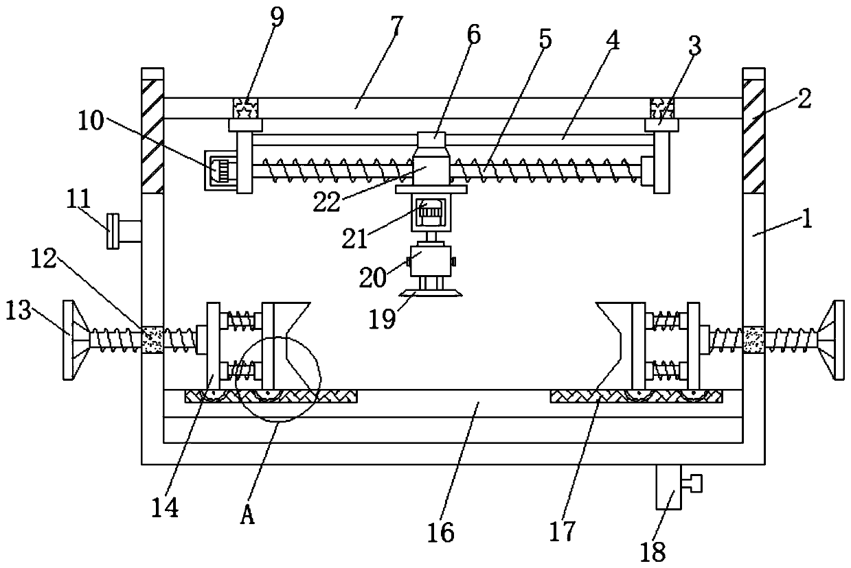
[0030] refer to Figure 1-3 , a grinding device for stone processing, comprising a box body 1, the inner walls of both sides of the box body 1 are connected with a placement plate 16 by bolts, and the top outer wall of the placement plate 16 is provided with a chute 17, the box body 1 The inner walls on both sides of the first electric slide rail 2 are connected by bolts, and the first electric slider is slidably connected to the inner wall on one side of the first electric slide rail 2, and the outer wall on one side of the first electric slider is connected by bolts. There is a connecting plate 7, and the bottom outer wall of the connecting plate 7 is connected with a second electric slide rail 9 by bolts, and the bottom inner wall of the second electric slide rail 9 is slidably connected with a second electric slide block, and the second electric slide block The bottom outer wall of the connecting rod 3 is connected with a connecting rod 3 by bolts, and the bottom outer wal...

Embodiment 2

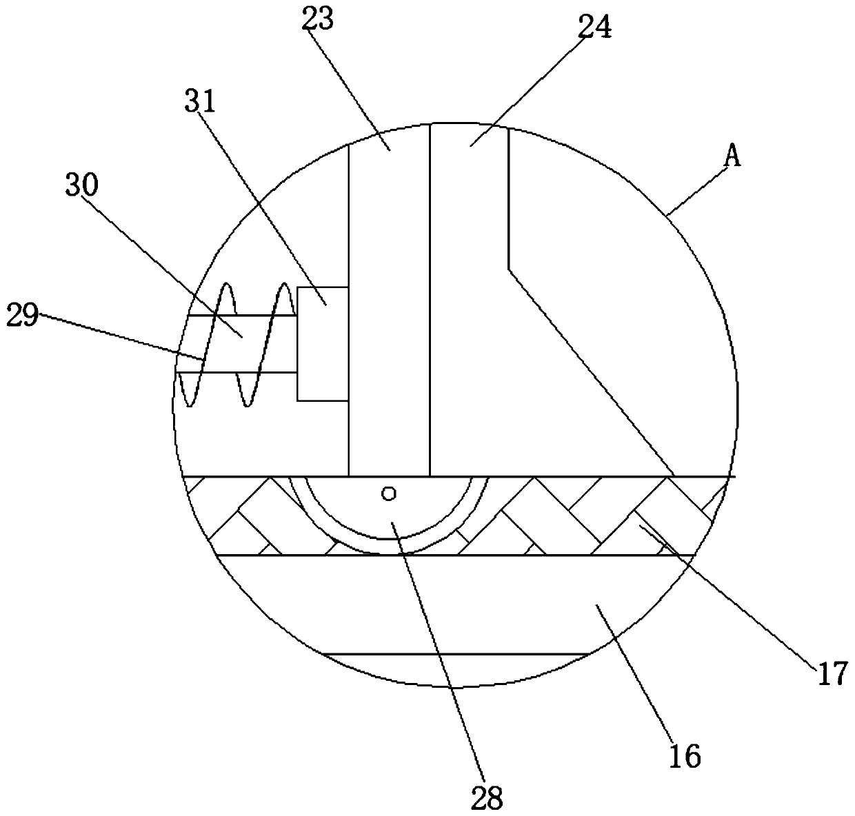
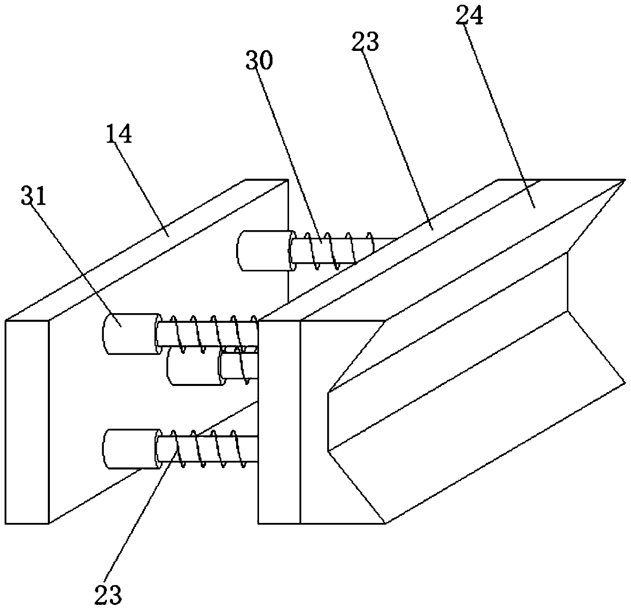
[0034] refer to Figure 4 , a grinding device for stone processing. Compared with Embodiment 1 in this embodiment, the outer wall of one side of the clamping block 24 is welded with bumps 25 distributed equidistantly, and the cross section of the bumps 25 is M-shaped.

[0035] Working principle: when in use, when people are grinding the stone, they can place the stone on the placement plate 16, and then pour water into the box 1 through the water inlet pipe 11 until the water submerges the top of the stone, and the grinding device grinds the stone in the water , not only can reduce the noise during grinding, but also avoid the dust generated during grinding from causing harm to people's bodies. Then people turn the screw body 13, and the screw body 13 drives the clamping block 24 to move until the stone body is fastened and fixed. The cross section of the protrusion 25 provided on the outer wall of one side of the holding block 24 is M-shaped, which can improve the fixing effect...


PUM


Abstract

The invention discloses a grinding device for stone machining. The grinding device comprises a box body, placing plates are arranged on the inner walls of the two sides of the box body, a sliding groove is formed in the outer wall of the top of each placing plate; a first electric sliding rail is arranged on the inner walls of the two sides of the box body. The inner wall of one side of the firstelectric sliding rail is slidably connected with a first electric sliding block. A connecting plate is arranged on the outer wall of one side of the first electric sliding block, a second electric sliding rail is arranged on the outer wall of the bottom of the connecting plate, a second electric sliding block is slidably connected to the inner wall of the bottom of the second electric sliding rail, and a connecting rod is arranged on the outer wall of the bottom of the second electric sliding block. When people grind stone, the stone can be placed on the placing plate, then water is injected into the box body through a water inlet pipe until the water submerges the top of the stone, and the grinding device grinds the stone in the water, so that the noise during grinding can be reduced, andthe harm of dust generated during grinding to the health of people can be avoided.

Description

technical field [0001] The invention relates to the technical field of stone processing, in particular to a grinding device for stone processing. Background technique [0002] At present, the grinding process of the stone equipment industry is mostly manual grinding and surface grinding. Manual grinding means manual hand-held angle grinder for stone grinding processing. In order to reduce the physical expenditure of work, large and medium-sized manual grinding machines use bellows to install the grinding machine on the grinding bed. The operator holds the grinding machine and presses it against the stone plate for grinding. For grinding large slabs, manual grinding depends on the skill of the operator, which is inefficient and labor-intensive, and the operator will directly inhale the dust during dry grinding. [0003] After retrieval, the Chinese Patent Publication No. is the patent of CN209078411U, which discloses a stone grinding device, including a frame frame; a base i...

Claims


Application Information

Patent Timeline
Patent Type & Authority Applications(China)
IPC IPC(8): B24B19/22B24B41/02B24B41/06B24B55/06B24B47/12B24B41/00
CPCB24B19/22B24B41/007B24B41/02B24B41/06B24B47/12B24B55/06
Inventor 周庆祥
Owner 周庆祥
Why Eureka
Try Eureka