Machine tool performance detection system and method

A detection system and machine tool technology, which is applied in the direction of measuring/indicating equipment, metal processing machinery parts, metal processing equipment, etc., can solve the problems of lack of measurement of key components of the brake, restrictions on the development of machine tool calibration and maintenance work, and achieve intuitive analysis of various item performance, simplify the performance testing process, and ensure the effect of accuracy and practicability

Inactive Publication Date: 2020-04-28
南京高嘉蕴机械工程有限公司
View PDF10 Cites 2 Cited by
  • Summary
  • Abstract
  • Description
  • Claims
  • Application Information

AI Technical Summary

Problems solved by technology

[0003] When the CNC machine tool brakes, the horizontal stability performance of each part of the machine tool, the local transmission workpiece, and the movement accuracy of the processing parts directly affect the processing quality. However, the existing performance detection methods that are satisfied with multi-axis drive machine tools lack the ability to monitor the performance of each system in the machine tool. The measurement of key moving parts restricts the calibration and maintenance of the machine tool. As the working hours go by, the machining accuracy and stability of the machine tool will directly restrict the processing yield of the product.

Method used


Image

  • Machine tool performance detection system and method
  • Machine tool performance detection system and method
  • Machine tool performance detection system and method

Examples


Embodiment 1

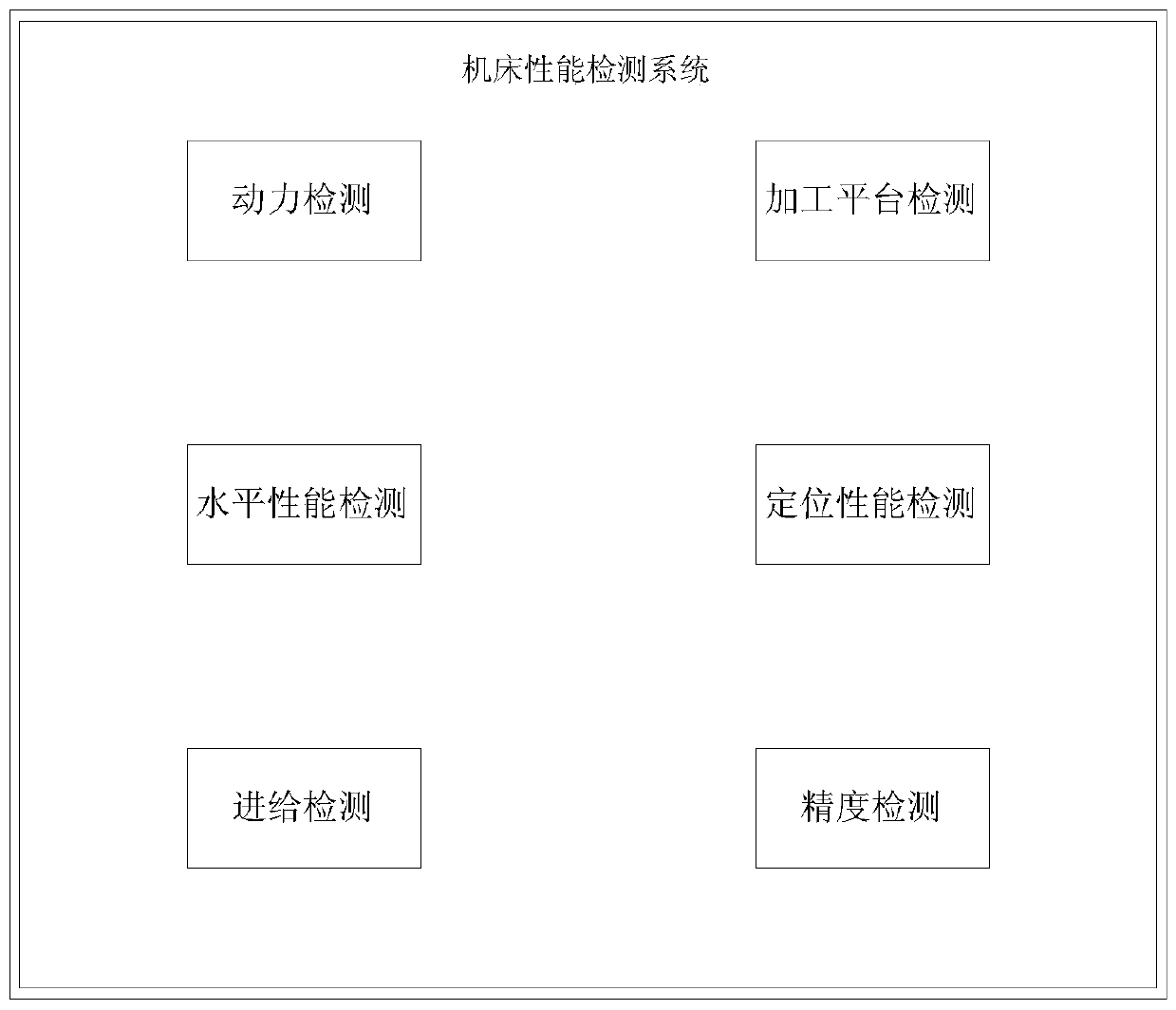
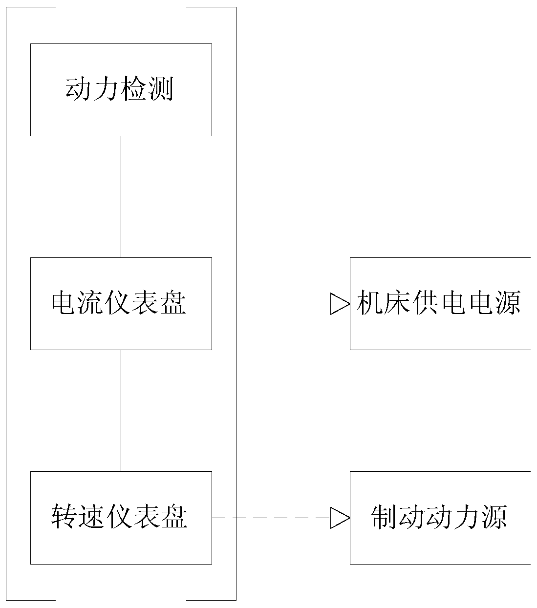
[0038] After turning off the power supply of the machine tool, set the current instrument panel in series between the transmission motor and the PLC industrial control module, and set the speed instrument panel in series between the transmission motor and the power supply line. The measurement specifications of the current instrument panel and the speed instrument panel depend on the machine tool. The power and the power of the brake motor are determined, and the speed instrument panel is selected according to the different brake power sources of the machine tool, and the selection specifications and types are not unique.

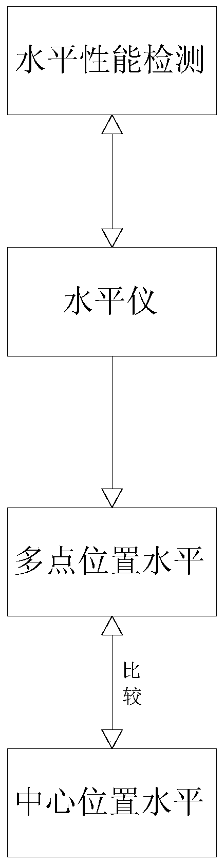
[0039] Horizontal performance testing is used to measure the corners of the machine tool, local horizontal position and horizontal stability. The horizontal performance testing includes a level gauge. The level gauge is set at each corner position of the machine tool processing area according to the horizontal height and length of the machine tool. The level ...

Embodiment 2

[0041] First set the level probe in the middle of the machine tool to reset the value to zero, and then set the level probe at the corner position of the machine tool. The measuring positions of the probes are distributed at equal intervals along the outer edge of the machine tool according to the total length of the machine tool. According to the level probe Record the horizontal position of the eight points of the machine tool to analyze the level of the machine tool by comparing the difference between the horizontal position height of the edge and the horizontal height of the center.

[0042] The feed detection is used to measure the stability of the track components in the X-axis, Y-axis, and Z-axis directions of the machine tool. The feed detection includes the PLC industrial control module of the machine tool. The feed detection controls the X-axis, Y-axis, and Z-axis track components of the machine tool through the PLC industrial control module. Here, the PLC industrial ...

Embodiment 3

[0045] By fixing multiple dial gauges at each corner of the processing platform, the horizontal height values ​​of each corner point of the processing platform are recorded by the dial gauge, and the inspectors analyze the processing platform through difference comparison.

[0046] The positioning performance test includes the processing head parts. The positioning performance test is used to measure the X-axis, Y-axis, Z-axis direction track in the machine tool, and the positioning performance of the processing head parts. The positioning performance test is based on the PLC industrial control module control in the feed test. The positioning performance The detection is based on the judgment of the stability of the X-axis, Y-axis, and Z-axis directions when the screw of the machine tool is active. Active location to analyze positioning performance through location difference comparison;

[0047] Accuracy detection is used to measure the position accuracy of track components a...


PUM


Abstract

The invention discloses a machine tool performance detection system and method, and belongs to the technical field of industrial detection. The machine tool performance detection system comprises power detection, horizontal performance detection, feed detection, machining platform detection, positioning performance detection and precision detection; and the power detection is used for determiningmachine tool braking power source stability, the power detection comprises a current instrument panel and a rotating-speed instrument panel, the current instrument panel is used for measuring currentdata between a braking power source and a power supply, the rotating speed instrument panel is used for measuring transmission rate data of the braking power source; the horizontal performance detection is used for determining the corners, the local horizontal position and horizontal stability of a machine tool, the horizontal performance detection comprises a level gauge, and the measurement of the reliability, stability and horizontal position of each assembling part of the machine tool is completed through the instrument panels, a dial indicator and the level gauge arranged in a front-and-rear fixed point mode. Comparative analysis can be conveniently carried out by the inspection personnel, the performance of the machine tool is obtained, output data intuitively reflects the performance of the machine tool, and subsequent correcting work can be conveniently carried out on the machine by the workers.

Description

technical field [0001] The invention relates to the technical field of industrial detection, in particular to a machine tool performance detection system and detection method. Background technique [0002] CNC machine tools are the foundation of modern machinery manufacturing. The precision of CNC machine tools will directly affect the quality of processed products. Now CNC machine tools mostly use multi-axis drive to satisfy the fixed-point movement of the axial track. Compared with traditional CNC machine tools, the multi-axis drive structure The position accuracy and horizontal stability performance will be more important; [0003] When the CNC machine tool brakes, the horizontal stability performance of each part of the machine tool, the local transmission workpiece, and the movement accuracy of the processing parts directly affect the processing quality. However, the existing performance detection methods that are satisfied with multi-axis drive machine tools lack the a...

Claims


Application Information

Patent Timeline
Patent Type & Authority Applications(China)
IPC IPC(8): B23Q17/00
CPCB23Q17/007
Inventor 江家鳌张洁陆才荣王靖
Owner 南京高嘉蕴机械工程有限公司
Why Eureka
Try Eureka