
Pneumatic strapping machine capable of preventing tape falling

A technology of a strapping machine and a cylinder, which is applied to the parts and packaging of the strapping machinery, can solve the problems of the strapping belt falling off, the length and size of the core structure being too large, etc.

Pending Publication Date: 2020-04-28
佛山轩珏科技有限公司
View PDF0 Cites 4 Cited by
  • Summary
  • Abstract
  • Description
  • Claims
  • Application Information

AI Technical Summary

Problems solved by technology

At present, most of the ordinary strapping machines on the market belong to imported technology. The tape cutting and bonding mechanism drives the cam assembly through the drive motor to realize the movement of the knife body, thereby completing the tape cutting and bonding actions, and binding the articles through the large swing rod. Tightening, due to the principle of design and structural problems, the length of the core structure is too large, which is limited in special industries and special application scenarios, and the phenomenon of strapping drop is common, requiring manual intervention to re-thread the strap
With the development of the times, the industry that has not yet adopted automatic strapping is precisely because it is restricted by the development of equipment and technology.

Method used


Image

  • Pneumatic strapping machine capable of preventing tape falling
  • Pneumatic strapping machine capable of preventing tape falling
  • Pneumatic strapping machine capable of preventing tape falling

Examples


Embodiment Construction

[0037] The specific embodiments of the present invention will be further described below in conjunction with the accompanying drawings. It should be noted here that the descriptions of these embodiments are used to help understand the present invention, but are not intended to limit the present invention. In addition, the technical features involved in the various embodiments of the present invention described below may be combined with each other as long as they do not constitute a conflict with each other.

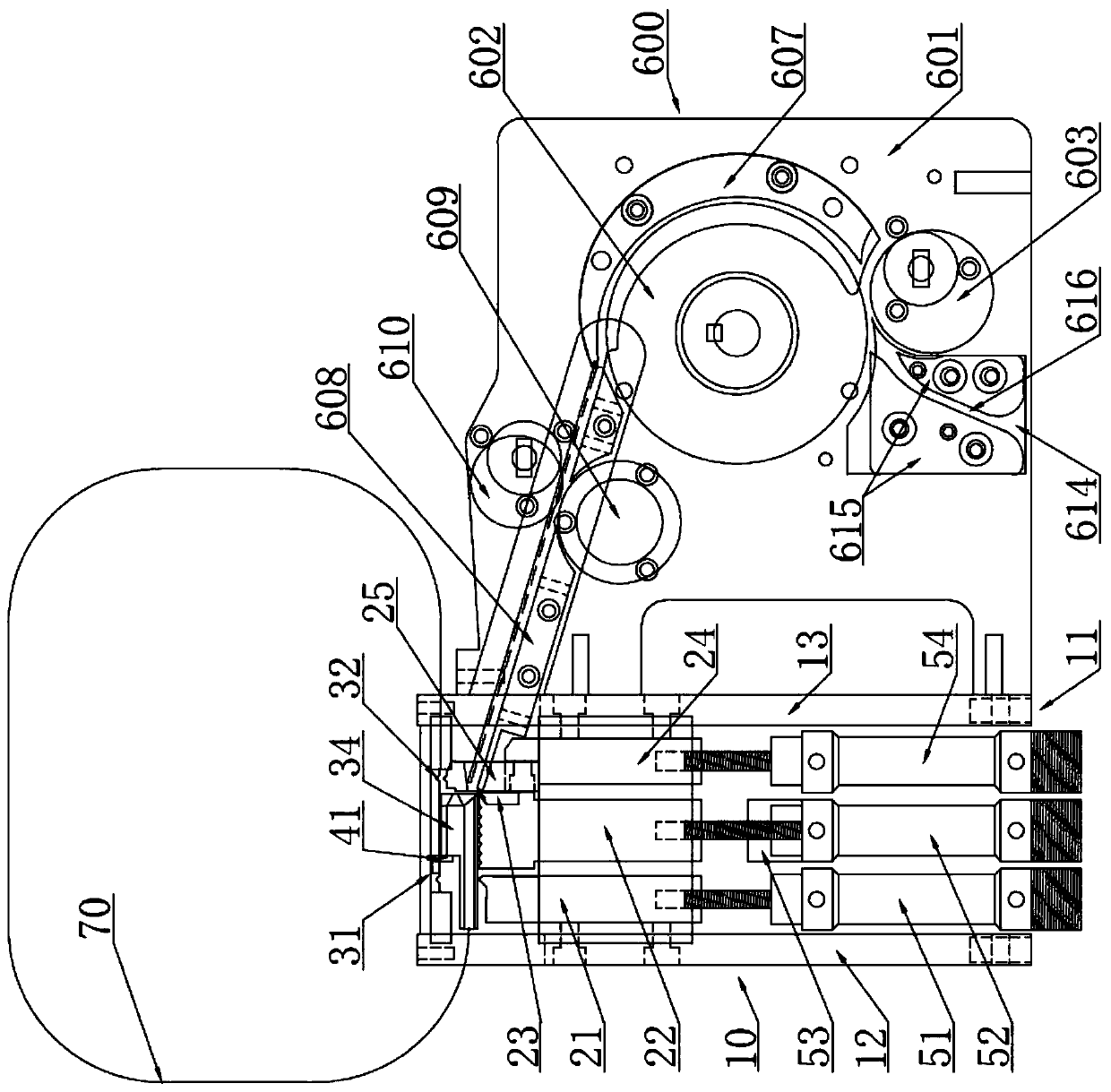
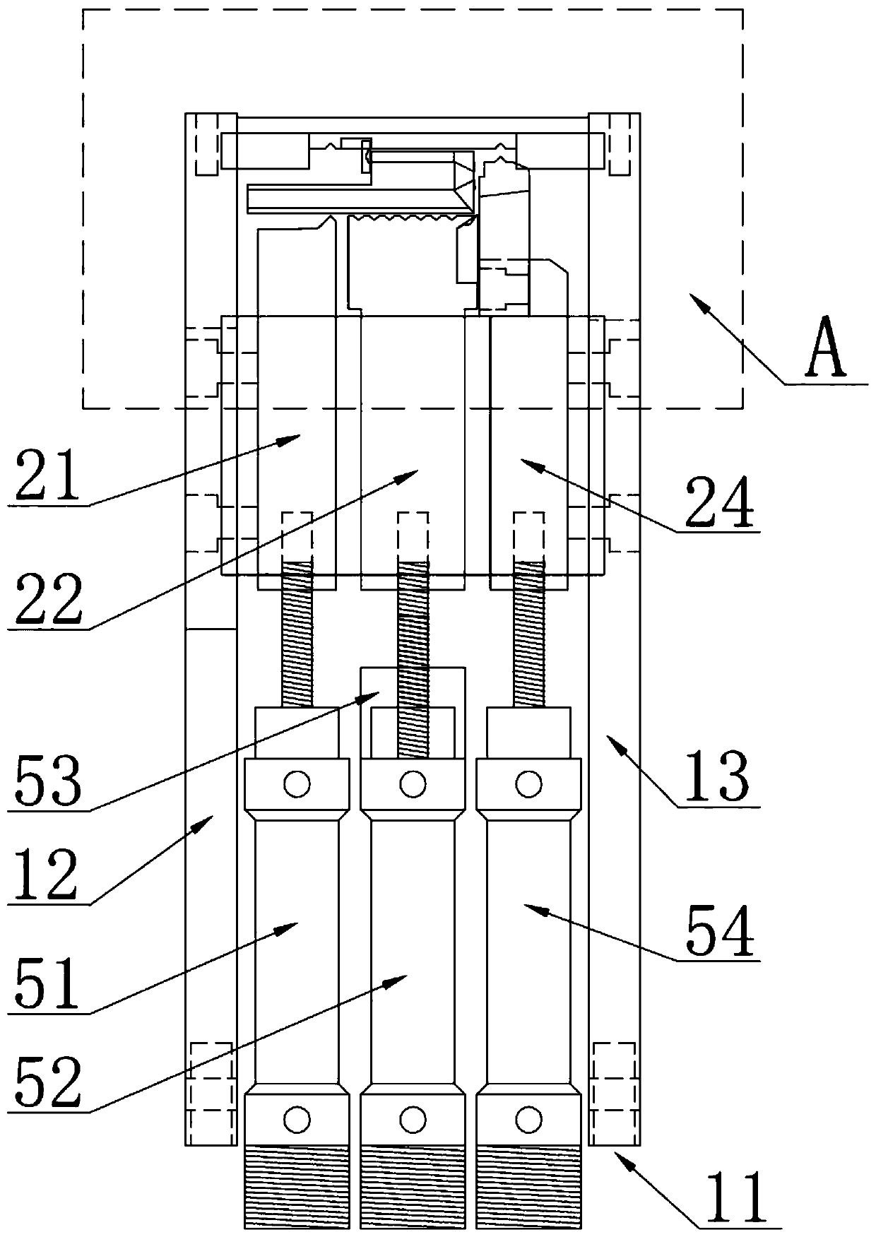
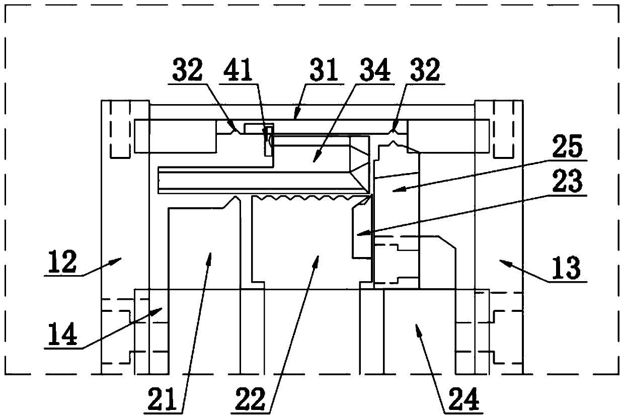
[0038] Such as Figure 1-7 As shown, a kind of non-drop pneumatic strapping machine provided by the present invention includes a strapping core 10, pushes the strapping strap into the strapping core 10 and reversely retracts the strap tightening mechanism 600, and is used to guide the strapping A closed loop belt channel 70 wrapped around the object to be bundled;

[0039] The strapping core 10 includes a base 11, a pressing and cutting mechanism, and a linkage cylinde...


PUM


Abstract

The invention discloses a pneumatic strapping machine capable of preventing tape falling, and belongs to the technical field of packaging machinery. The machine comprises a strapping machine core anda tape feeding and withdrawing tightening mechanism; and the strapping machine core comprises a base, a pressing tape cutting mechanism and a linkage air cylinder set, wherein the pressing tape cutting mechanism is movably arranged on the base and driven by the linkage air cylinder set. According to the machine, the technical scheme that the pressing tape cutting mechanism is driven by the linkageair cylinder set is adopted to replace the technical scheme that in the prior art, the pressing tape cutting mechanism is driven by a motor and a cam set drive, and moreover, an auxiliary mechanism required for driving the pressing tape cutting mechanism by adopting the motor and the cam set is cancelled, so that mounting hole sites formed in the base are greatly reduced, the machining difficultyof the base is reduced, and more accommodating space can be vacated in the base; and correspondingly, the length size of the strapping machine core is shortened on the whole, so that the structure weight of the machine core is reduced, and the strapping machine can be applied to more special industries and special application scenes.

Description

technical field [0001] The invention relates to the technical field of packaging machinery, in particular to a non-drop pneumatic strapping machine. Background technique [0002] Strapping machines are widely used in various industries. In order to avoid product damage during transportation and handling, all products require different degrees of outer packaging, and the products are externally bundled with packing tape. Bundled products are not only conducive to their transportation and handling during circulation, avoiding product damage, but also improve the convenience of storage and reduce the space occupied by storage. At present, most of the ordinary strapping machines on the market belong to imported technology. The tape cutting and bonding mechanism drives the cam assembly through the drive motor to realize the movement of the knife body, thereby completing the tape cutting and bonding actions, and binding the articles through the large swing rod. Tightening, due t...

Claims


Application Information

Patent Timeline
Patent Type & Authority Applications(China)
IPC IPC(8): B65B13/32B65B61/06B65B13/18
CPCB65B13/32B65B61/06B65B13/18
Inventor 赵志文
Owner 佛山轩珏科技有限公司
Learn More