Rock debris flow measuring device and method

A flow measurement device and cuttings technology, which is applied in the field of oil drilling, can solve the problems of slow turning speed, uncontrollability, and influence on collection and measurement, and achieve the effects of weight reduction, convenient handling and installation, and simplified external connections

Pending Publication Date: 2020-04-28
中国电波传播研究所
View PDF0 Cites 3 Cited by
  • Summary
  • Abstract
  • Description
  • Claims
  • Application Information

AI Technical Summary

Problems solved by technology

[0003] In the existing analysis device, after the cuttings are collected, it needs to be turned over by the gravity of the sand fishing tank itself, so that the cuttings are poured out, which is uncontrollable due to the influence of the center of grav

Method used


Image

  • Rock debris flow measuring device and method
  • Rock debris flow measuring device and method
  • Rock debris flow measuring device and method

Examples


Embodiment 1

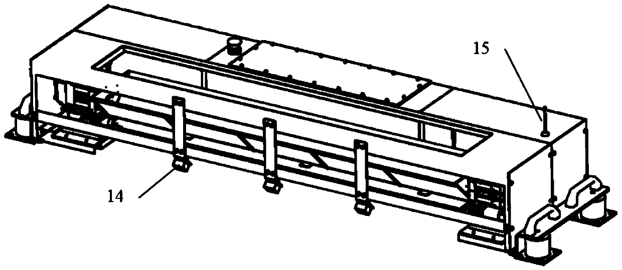
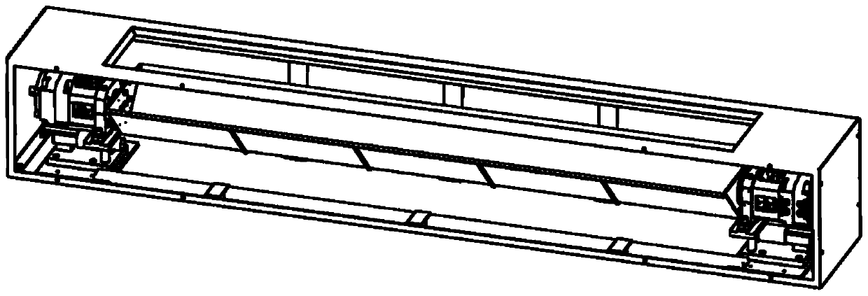
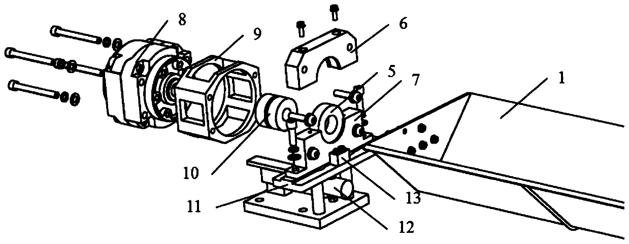
[0029] Example 1, such as Figure 1-5 As shown, this embodiment discloses a cuttings flow measurement device, which includes the outer skeleton of the weighing sand dumping assembly and the control box connected together, and a load cell is installed on the bottom of both sides of the outer skeleton of the weighing sand dumping assembly 12, and the bearing bracket mounting plate 11 is installed on the load cell, the bearing bracket is installed on the bearing bracket mounting plate, and the bearing 5 is installed in the bearing mounting hole on the bearing bracket by interference fit, on the inner side of the bearing bracket Block 13 is installed, the cylinder installation frame 9 is installed on the outside, and the rotary cylinder 8 is installed in the cylinder installation frame. A collision block 3 and a support shaft 4 are respectively installed on both sides of the V-shaped groove 1, and the two support shafts are inserted respectively. The adjacent bearings are connecte...


PUM


Abstract

The invention discloses a rock debris flow measuring device and method. The rock debris flow measuring device comprises a weighing and sand pouring assembly outer framework and a control box which areconnected together. A weighing sensor is arranged at each of the bottoms of the two sides of the weighing and sand pouring assembly outer framework. Bearing support installation plates are installedon the weighing sensors, bearing supports are installed on the bearing support installation plates, and bearings are installed in bearing installation holes in the bearing supports in an interferencefit mode. Check blocks are installed on the inner sides of the bearing supports, air cylinder installation frames are installed on the outer sides of the bearing supports, and rotary air cylinders areinstalled in the air cylinder installation frames. According to the rock debris flow measuring device, wireless communication and battery power supply modes are adopted, external connection of the measuring device is greatly simplified, the rock debris flow measuring device can work only by being externally connected with one power gas pipeline, and field installation is facilitated; and the sandpouring and resetting are pneumatically driven, so that compared with motor driving, the weight of the measuring device is greatly reduced, and on-site carrying and mounting are facilitated. The rotary air cylinders directly drive a sand receiving disc to pour sand and reset, and the driving mode is simple and reliable.

Description

technical field [0001] The invention belongs to the field of petroleum drilling, in particular to a cuttings flow measuring device and a measuring method in the field. Background technique [0002] In the process of drilling construction, especially in highly deviated wells and horizontal wells, the cleanliness of the wellbore is an important factor affecting the safety of drilling construction and the efficiency of drilling. In highly deviated well sections and horizontal well sections, the sedimentation direction of cuttings is along the direction of gravity, while the component of annular flow velocity along the direction of gravity is very small, or even zero, and the ability of drilling fluid to carry cuttings is reduced, resulting in cuttings being easily A bed of cuttings is deposited on the lower borehole wall. The cuttings bed will have a serious impact on the drilling operation, and it is easy to cause drilling accidents such as drill sticking, which greatly restr...

Claims


Application Information

Patent Timeline
IPC IPC(8): G01F1/78G01G13/00
CPCG01F1/78G01G13/00
Inventor 肖敬涛张增旺宋建军沈铁
Owner 中国电波传播研究所
Why Eureka
Try Eureka