

Shock tube for dynamic pressure calibrating device
A verification device and dynamic pressure technology, applied in the field of shock tubes, can solve the problems of cumbersome preparation process and difficult clamping of the diaphragm, so as to meet the test requirements, facilitate loading and unloading, and facilitate the test operation
- Summary
- Abstract
- Description
- Claims
- Application Information
AI Technical Summary
Problems solved by technology
Method used
Image

Examples
Embodiment
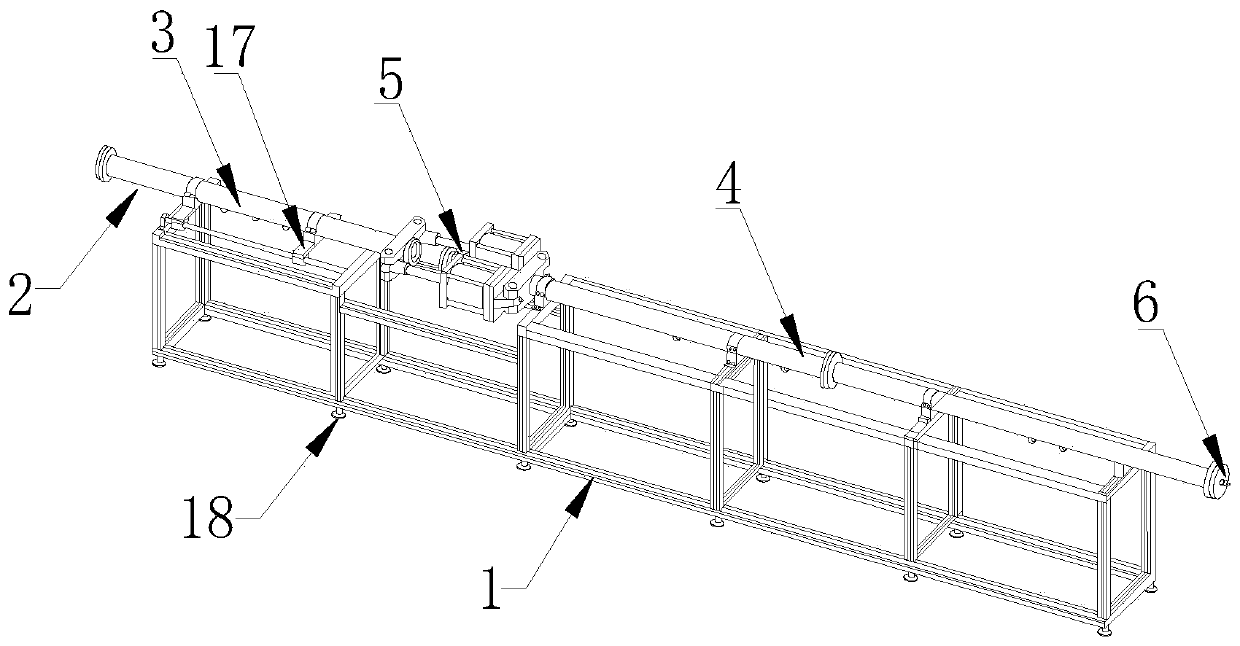
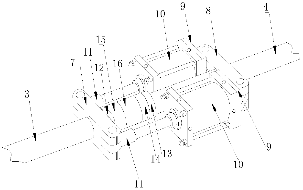
[0025] Embodiment: a kind of shock tube used for dynamic pressure verification device, such as figure 1 , figure 2 and image 3 As shown, it includes a base support frame 1 and a shock tube body 2 fixedly connected to the top of the base support frame 1. The shock tube body 2 includes a high-pressure section 3 and a low-pressure section 4; the high-pressure section 3 and the low-pressure section 4 are installed There is a clamping mechanism 5; the end of the low-voltage section 4 away from the clamping mechanism 5 is equipped with a sensor 6 to be detected; the clamping mechanism 5 includes a first fixed seat 7 fixedly connected to the outer wall of the high-voltage section 3 ends, and a first fixed seat 7 connected to the end of the low-voltage section 4 The second fixed seat 8 fixedly connected to the outer wall, the ear seat 9 connected with the second fixed seat 8, and the two cylinders 10 fixedly connected with the ear seat 9 respectively located on both sides of the hi...
PUM
| Property | Measurement | Unit |
|---|---|---|
| Outer diameter | aaaaa | aaaaa |
| The inside diameter of | aaaaa | aaaaa |
| Length | aaaaa | aaaaa |
Abstract
Description
Claims
Application Information