Gas nozzle quick change method and device for laser equipment

A gas nozzle and air flotation technology, which is used in laser welding equipment, welding equipment, metal processing equipment, etc., can solve the problems of inability to process, affect the processing effect, reduce the processing efficiency and effect, etc., to ensure consistency and work stability. Good, improve the effect of processing efficiency and quality

Active Publication Date: 2020-09-29
SONGSHAN LAKE MATERIALS LAB +1
View PDF17 Cites 0 Cited by
  • Summary
  • Abstract
  • Description
  • Claims
  • Application Information

AI Technical Summary

Problems solved by technology

[0003] For laser processing on complex special-shaped surfaces, the air nozzle will interfere with the workpiece. At this time, the coaxial air nozzle cannot be used, and only the side-axis air nozzle can be used for side-axis blowing processing. This blowing method will reduce the processing time. Efficiency and effect are more serious. If the position and angle of the side-axis air nozzle are not appropriate, the residue in the microhole cannot be discharged in time, and the laser energy cannot effectively act on the predetermined area, resulting in a situation that cannot be processed.
However, the angle of the existing side-axis air nozzle cannot be automatically switched and adjusted. For this reason, the angle and position of the universal bamboo joint air pipe can only be manually adjusted to perform side-axis auxiliary blowing. The existing problems are: manual adjustment and replacement are necessary, At this time, the processing machine tool needs to stop the processing process, and the processing can only be continued after manual adjustment to the specified position and angle. At the same time, the consistency of each adjustment position cannot be guaranteed, which will affect the processing effect.

Method used


Image

  • Gas nozzle quick change method and device for laser equipment
  • Gas nozzle quick change method and device for laser equipment
  • Gas nozzle quick change method and device for laser equipment

Examples


Embodiment

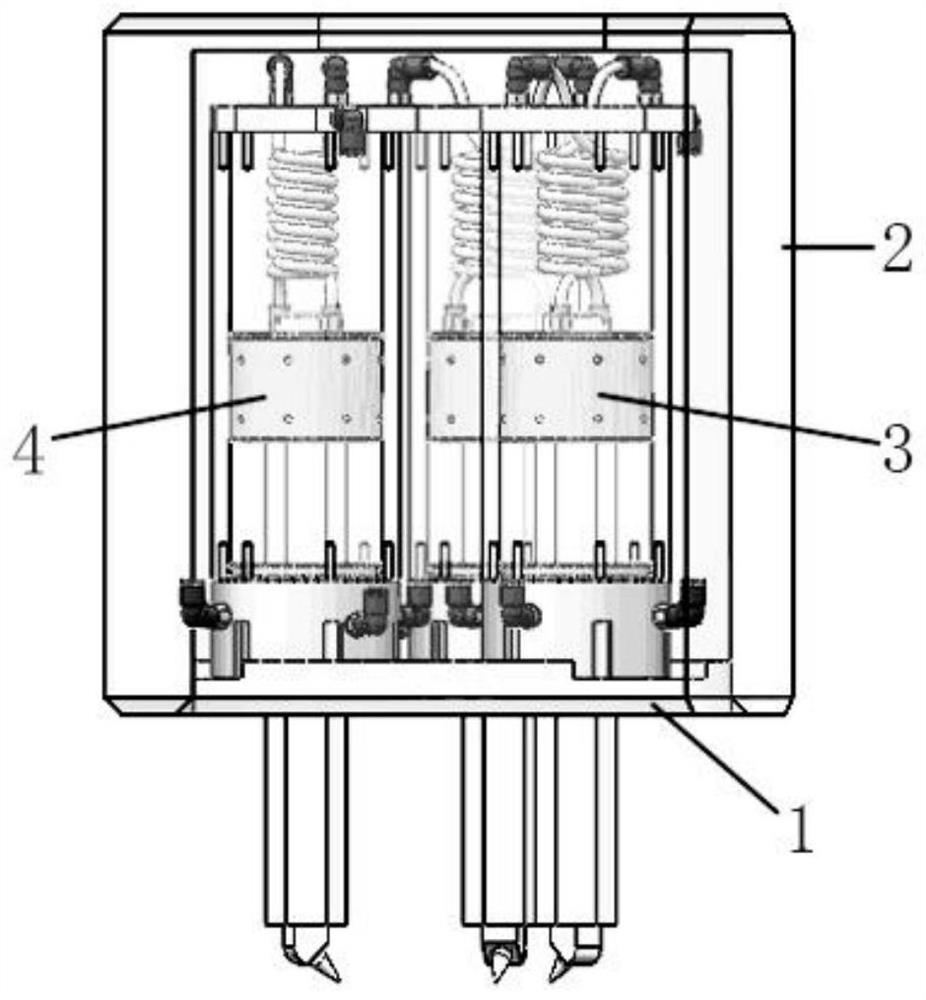
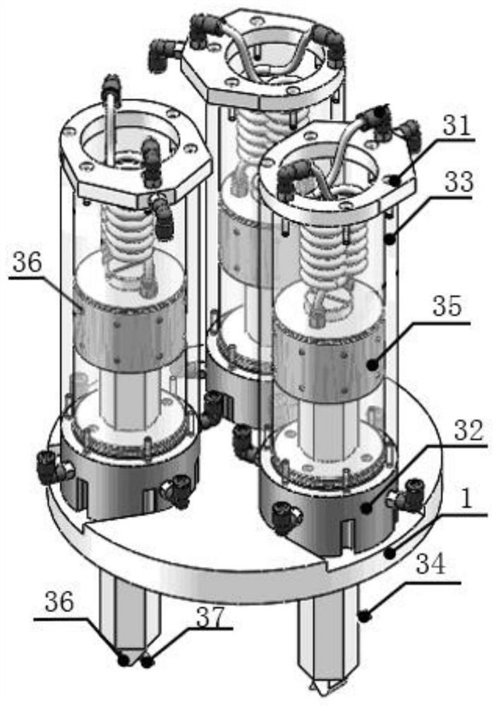
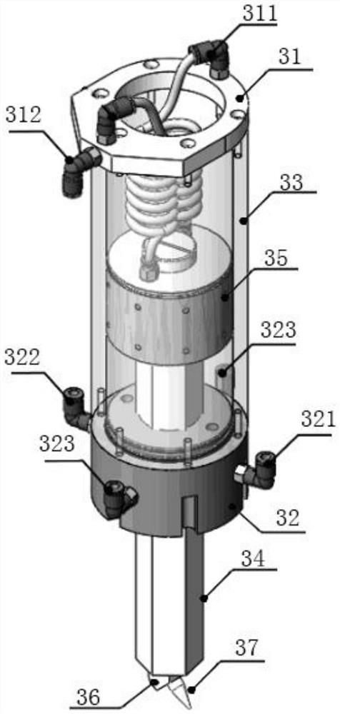
[0035] Example: see Figure 1-Figure 4 , a quick-change air nozzle device provided in this embodiment, which includes a base plate 1, a housing 2, and at least two side-axis quick-change air nozzle assemblies 3 arranged on the base plate 1, at the center of the bottom surface of the base plate, a The electromagnetic locking device 4 is used to absorb or release the coaxial air nozzle 5 .

[0036] In this embodiment, three side-axis quick-exchange nozzle assemblies 3 are symmetrically arranged on the bottom surface of the base plate. In other embodiments, the number of side-axis quick-change air nozzle assemblies 3 can also be two, four or more. The working heights and angles of the air nozzles on each side shaft quick-change air nozzle assembly 3 are different. That is, the lengths of the air-floating piston rods in each side-axis quick-change air nozzle assembly 3 are different; the orientations of the air nozzles in each side-axis quick-change air nozzle assembly 3 are dif...


PUM


Abstract

The invention discloses a rapid replacement method and device of gas nozzles of a laser device. The rapid replacement method and device of the gas nozzles of the laser device comprises a base plate and at least two paraxial rapid replacement gas nozzle assemblies arranged on the base plate. The work heights and the angles of the gas nozzles on all the paraxial rapid replacement gas nozzle assemblies are all different. Each paraxial rapid replacement gas nozzle assembly comprises an upper end cover, a lower end cover, a gas flotation cylinder body, a gas flotation piston rod, a gas flotation piston, a gas nozzle connector and a gas nozzle. According to the rapid replacement method of the gas nozzles of the laser device, by switching the paraxial rapid replacement gas nozzle assemblies at different positions to enter the work state, the purpose of rapid replacement of the gas nozzles is achieved. After the rapid replacement device of the gas nozzles is installed on the laser device, switching can be conducted between all the paraxial rapid replacement gas nozzle assemblies and between the paraxial rapid replacement gas nozzle assemblies and a coaxial gas nozzle, manual intervention is not needed, and then rapid, accurate and automatic replacement of the gas nozzles is achieved; besides, the angle and position consistency is effectively guaranteed during each replacement of the gas nozzles, the work stability is good, secondary adjustment is not needed, and the machining efficiency and quality are effectively improved.

Description

technical field [0001] The invention relates to the technical field of laser processing, in particular to a method and device for quickly changing gas nozzles of laser equipment. Background technique [0002] The advantages of laser processing in the process of non-contact and no need for liquid acid-base assistance are being used more and more. In the process of laser microhole processing, the gas nozzle is used for the gas jet. On the one hand, it is to prevent the focusing optical system from being polluted by the injection material; on the other hand, it is to increase the injection rate of the removal material and improve the processing efficiency. At present, the coaxial gas nozzle is widely used, that is, the light and gas are coaxial. During the processing, the high-pressure gas ejected through the gas nozzle will bring out the residue and plasma inside the micropore. [0003] For laser processing on complex and special-shaped surfaces, the air nozzle will interfere...

Claims


Application Information

Patent Timeline
Patent Type & Authority Patents(China)
IPC IPC(8): B23K26/14
CPCB23K26/1482
Inventor 赵卫王海龙郭亚文王绍鹏朱建海
Owner SONGSHAN LAKE MATERIALS LAB
Why Eureka
Try Eureka