Working condition self-adaptation high-speed milling machining process tool monitoring method and system

A high-speed milling and machining process technology, applied in the direction of manufacturing tools, metal processing equipment, metal processing machinery parts, etc., can solve the problem that the algorithm model cannot be adapted, cannot effectively process the time series, and the accuracy of wear state recognition is low. The effect of improving the ability to adapt to multiple working conditions, improving the monitoring accuracy, and improving the recognition accuracy

Inactive Publication Date: 2020-05-01
NANJING UNIV OF AERONAUTICS & ASTRONAUTICS
View PDF18 Cites 14 Cited by
  • Summary
  • Abstract
  • Description
  • Claims
  • Application Information

AI Technical Summary

Problems solved by technology

Since tool wear is a time-series and irreversible process, commonly used algorithm models such as artificial neural networks and support vector machines cannot effectively process time series; at the same time, when the working conditions change (cutting conditions, tool size, etc.), based on the original The algorithm model of working condition training cannot adapt to the current changing working conditions, resulting in low accuracy of wear state recognition

Method used


Image

  • Working condition self-adaptation high-speed milling machining process tool monitoring method and system
  • Working condition self-adaptation high-speed milling machining process tool monitoring method and system
  • Working condition self-adaptation high-speed milling machining process tool monitoring method and system

Examples


Embodiment 1

[0055] A working condition self-adaptive tool monitoring method for high-speed milling, comprising the following steps:

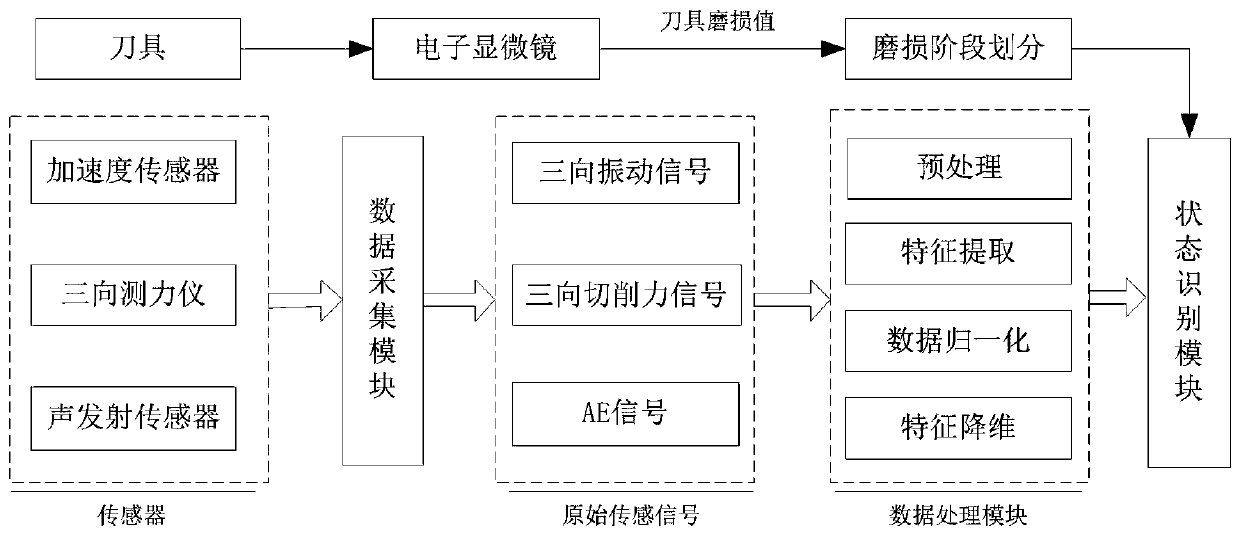
[0056] Step 1: Obtain raw sensor signals and measure tool wear

[0057] Such as figure 1 As shown, multiple groups of milling experiments were implemented, and the three-way vibration signals, three-way cutting force signals and one-way acoustic emission signals under different milling conditions were collected through the data acquisition module; at the same time, the actual wear of the tool was measured by an electron microscope, and the measured values ​​were saved. The obtained sensor signal and the actual wear amount of the tool.

[0058] Step 2: Signal preprocessing and feature extraction

[0059] The collected raw sensing signals are preprocessed and the time domain, frequency domain and time-frequency domain features of each signal are extracted respectively. Time domain features include: mean, peak, peak-to-peak, rms, slope, kurtosis, kurtosis f...

Embodiment 2

[0083] Such as image 3 As shown, a system for realizing the tool monitoring method of high-speed milling process adaptive to working conditions, including:

[0084] Acceleration sensor for monitoring and sending three-way vibration signals under different milling conditions (measuring x, y, z three-way vibration signals);

[0085] Three-way dynamometer for monitoring and sending three-way cutting force signals under different milling conditions;

[0086] Acoustic emission sensors for monitoring and sending unidirectional acoustic emission signals under different milling conditions;

[0087] The data acquisition module is used to collect three-way vibration signals, three-way cutting force signals and one-way acoustic emission signals under different milling conditions;

[0088] Electron microscope, used to measure the actual wear of the tool;

[0089] Data processing module for signal preprocessing, feature extraction and related processing;

[0090] The state identificat...


PUM


Abstract

The invention discloses a working condition self-adaptation high-speed milling machining process tool monitoring method. The method comprises the following steps of firstly, original sensing signal obtaining, and tool wear amount measuring; secondly, signal pretreatment and characteristic extracting; thirdly, characteristic dimensionality reduction; fourthly, wear stage division; fifthly, model parameter training; and sixthly, wear state identifying. Meanwhile, the invention discloses a system achieving the above method. Online working condition self-adaptation monitoring of the tool wear state can be achieved, the tool wear state monitoring accuracy rate is improved, production cost is effectively reduced, and production efficiency and production quality are improved.

Description

technical field [0001] The invention relates to the field of mechanical processing state monitoring, mainly a tool wear state monitoring method and system, in particular to a working condition self-adaptive high-speed milling process tool monitoring method and system. Background technique [0002] Tool wear is a common phenomenon in the high-speed CNC milling process of difficult-to-machine materials, and it continues to increase with the increase of processing time, which is an irreversible process. As a key component of CNC machine tools, cutting tools with different degrees of wear have an important impact on the accuracy, efficiency and production benefits of machined parts. According to industrial statistics, the proportion of scrapped parts and machine tool shutdown due to excessive tool wear and failure to be detected in time reaches 1 / 3. In addition, tool wear has an important impact on the life of the machine tool and even the personal safety of the operator. Ther...

Claims


Application Information

Patent Timeline
Patent Type & Authority Applications(China)
IPC IPC(8): B23Q17/09
CPCB23Q17/0957
Inventor 杨文安刘伟超王鹏宇
Owner NANJING UNIV OF AERONAUTICS & ASTRONAUTICS
Why Eureka
Try Eureka