
Forming method and forming tooling of a composite material c-shaped beam

A composite material and molding method technology, applied to household appliances, other household appliances, household components, etc., can solve problems such as unfavorable manufacturing efficiency and manufacturing accuracy, influence of C-beam molding quality, easy generation of wrinkles and bending, etc. Improve the curing effect, simplify the molding difficulty, and improve the molding quality

Active Publication Date: 2021-07-20
COMAC +1
View PDF3 Cites 0 Cited by
  • Summary
  • Abstract
  • Description
  • Claims
  • Application Information

AI Technical Summary

Problems solved by technology

However, when the C-type blank is transferred to the curing tooling, it needs to be repositioned, and the operation is complicated, which is not conducive to improving manufacturing efficiency and manufacturing accuracy. In the transfer process, the C-type blank is prone to wrinkles and folds due to its thin wall thickness. Defects such as bending will have a great impact on the final forming quality of the C-beam

Method used


Image

  • Forming method and forming tooling of a composite material c-shaped beam
  • Forming method and forming tooling of a composite material c-shaped beam
  • Forming method and forming tooling of a composite material c-shaped beam

Examples


Embodiment Construction

[0038] The technical solutions of the present invention will be further described below in conjunction with the accompanying drawings and through specific implementation methods.

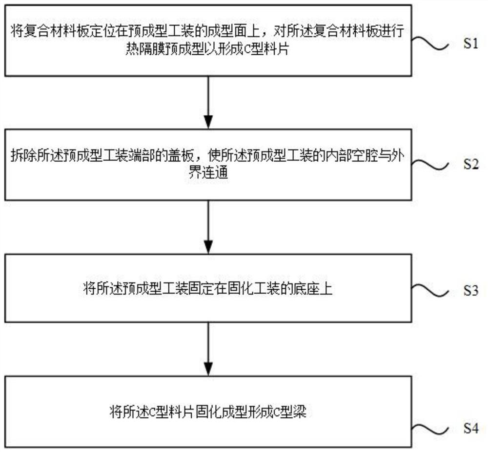
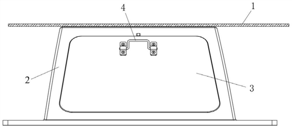
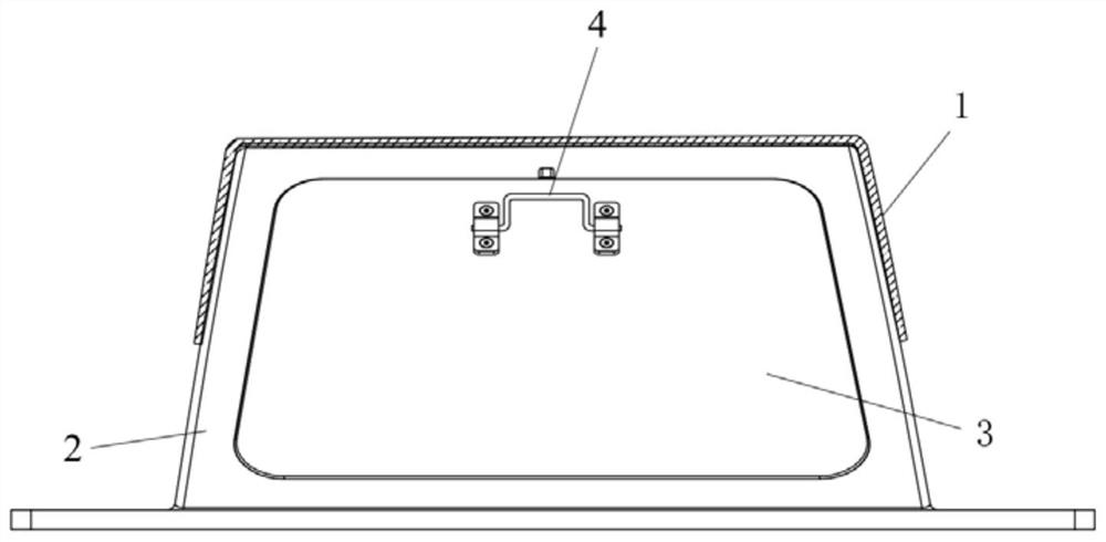
[0039] This embodiment provides a method for forming a composite C-beam. By using this forming method, the composite material plate 1 can be made into a C-beam required on aircraft and other equipment. The C-beam has a "C"-shaped structure as a whole. It includes a top plate and two side plates protruding from both ends of the top plate. Specifically, such as figure 1 As shown, the molding method specifically includes the following steps:

[0040] S1. Positioning the composite material plate 1 on the forming surface of the preforming tooling 2, performing thermal diaphragm preforming on the composite material plate 1 to form a C-shaped blank;

[0041] S2. Remove the cover plate 3 at the end of the preforming tooling 2, so that the internal cavity 201 of the preforming tooling 2 communicates with t...


PUM


Abstract

The invention discloses a molding method and a molding tool for a composite material C-shaped beam, belonging to the technical field of composite material molding. The forming method provided by the present invention includes the following steps: S1, positioning the composite material plate on the forming surface of the preforming tooling, and performing thermal diaphragm preforming on the composite material plate to form a C-shaped tablet; S2, removing the The cover plate at the end of the preformed tooling communicates the internal cavity of the preformed tooling with the outside world; S3, fixing the preformed tooling on the base of the curing tooling; S4, solidifying and molding the C-shaped material form a C-beam. This forming method not only avoids the secondary positioning and simplifies the manufacturing difficulty by moving the preformed tooling and the C-shaped blank as a whole, but also avoids the phenomenon of wrinkles and bending caused by transferring the C-shaped blank alone, and improves the C Forming quality of beams.

Description

technical field [0001] The invention relates to the technical field of composite material forming, in particular to a forming method and forming tooling of a composite material C-shaped beam. Background technique [0002] Composite materials are materials with new properties composed of two or more materials with different properties through physical or chemical methods. With the rapid development of composite material manufacturing technology, composite materials have been widely used in the field of civil aviation. The three main structural parts of the aircraft, including wall panels, long trusses and beams, can all be made of composite materials. [0003] The C-beam made of composite material is an important structural part on the aircraft. In the prior art, the thermal diaphragm process is generally used to manufacture the C-beam. The traditional thermal diaphragm process includes two processes of preforming and forming. Each process has a corresponding tooling. After ...

Claims


Application Information

Patent Timeline
Patent Type & Authority Patents(China)
IPC IPC(8): B29C70/38B29C70/34B29L31/30
CPCB29C70/342B29C70/38B29L2031/3076
Inventor 沈卫国刘卫平陈菲晏冬秀孙凯赵科新肖清明余永波赵强徐鹏
Owner COMAC
Learn More