Screw conveyor used in wet material smashing process

A screw conveyor, wet material technology, applied in the field of mechanical conveying, can solve the problems of uneven heating, difficult cleaning, agglomeration and agglomeration, and achieve the effect of improving the utilization rate of heat source, convenient and fast cleaning, and fast and uniform heating

Inactive Publication Date: 2020-05-01
李晓睿
View PDF12 Cites 4 Cited by
  • Summary
  • Abstract
  • Description
  • Claims
  • Application Information

AI Technical Summary

Problems solved by technology

[0004] 1. The existing screw conveyor does not filter and pulverize the conveyed wet material in the process of conveying the wet material. With the extension of the running time, the large wet material is easily agglomerated by the extrusion and friction of the auger Agglomeration can easily cause the feeding screw to be stuck, or even the shaft of the feeding screw to be twisted off;
[0005] 2. Most of the existing screw conveyors do not have a temperature control device for the wet material for making fertilizers, but the heating device for the screw conveyor is heated by setting a heating collar on the outer wall of the feeding cylinder, not only It causes a large waste of heat source, and at the same time causes the raw materials in the cylinder to be heated slowly and unevenly;
[0006] 3. The existing screw conveyor does not have a moisture adjustment device for the wet material used for fertilizer production, which is not conducive to controlling the temperature and moisture required for wet material granulation, and has great limitations. At the same time, the existing screw conveyor is It is difficult to clean the cylinder wall after feeding, and it needs to be disassembled for cleaning, which is time-consuming and laborious

Method used


Image

  • Screw conveyor used in wet material smashing process
  • Screw conveyor used in wet material smashing process
  • Screw conveyor used in wet material smashing process

Examples


Embodiment Construction

[0041] The following will clearly and completely describe the technical solutions in the embodiments of the present invention with reference to the accompanying drawings in the embodiments of the present invention. Obviously, the described embodiments are only some, not all, embodiments of the present invention. Based on the embodiments of the present invention, all other embodiments obtained by persons of ordinary skill in the art without making creative efforts belong to the protection scope of the present invention.

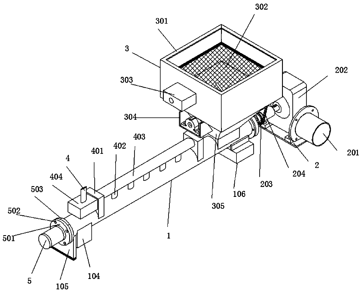
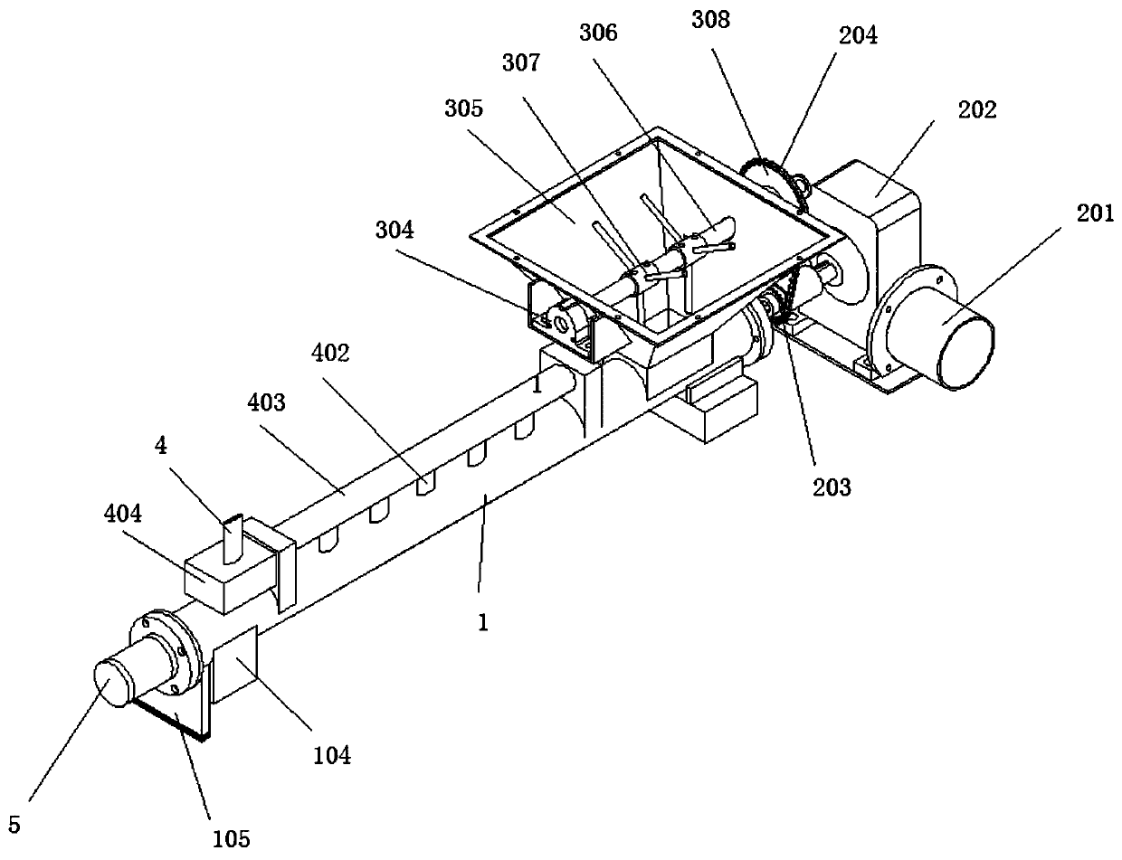
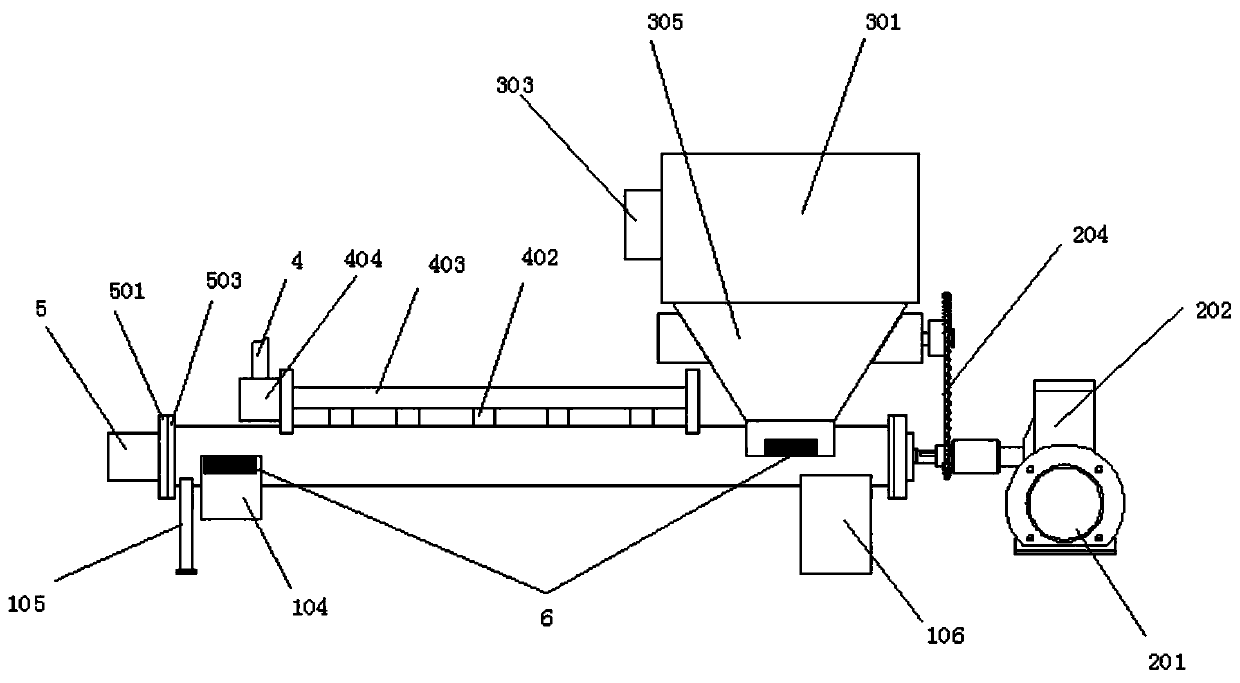
[0042] see Figure 1-9 , in the embodiment of the present invention, a screw conveyor used in the crushing process of wet materials includes a feeding barrel 1, and the inside of the feeding barrel 1 is provided with a feeding screw 1 101 and a feeding screw 2 107. The first feeding screw 101 is a hollow structure without a cover at one end, and the first auger 102 is arranged on the annular surface of the first feeding screw 101, and the second auger 108 is a...


PUM


Abstract

The invention discloses a screw conveyor used in the wet material smashing process. A first material conveying screw rod and a second material conveying screw rod are arranged in a material conveyingcylinder side by side, and a first auger and a second auger are arranged on the ring-shaped face of the first material conveying screw rod and the ring-shaped face of the second material conveying screw rod correspondingly. A feeding box is arranged on the top of the arc side face of the end, close to a motor installation seat, of the material conveying cylinder in an erected manner, and a storagebattery is connected to the end face of the end, away from the motor installation seat, of the material conveying cylinder. An external connection water conveying pipeline is fixedly arranged above the arc side face of the material conveying cylinder. The first material conveying screw rod is arranged to be of a hollow structure, and a heating pipe is arranged in the hollow structure of the firstmaterial conveying screw rod. Fertilizer wet materials in the material conveying cylinder are heated according to the temperature needed during fertilizer wet material pelletizing, the quality of fertilizer pelletizing is improved, the humidity of the fertilizer wet materials in the material conveying cylinder is controlled by controlling the external connection water conveying pipeline, the screw conveyor can be used for regulating the temperature and water in the material conveying process, and the practicability of the screw conveyor is improved.

Description

technical field [0001] The invention belongs to the technical field of mechanical conveying, in particular to a screw conveyer used in the crushing process of wet materials. Background technique [0002] Screw conveyor is a commonly used powder conveying equipment. It is widely used in various production fields because of its large conveying capacity, good sealing performance and high efficiency. Its principle is to use the motor to drive the screw to rotate and push the material to achieve the purpose of conveying. It can be transported horizontally, inclined or vertically, and has the advantages of simple structure, small cross-sectional area, good sealing, convenient operation, easy maintenance, and convenient closed transportation. [0003] The mechanization of agricultural production requires fertilizers to be granulated and spherical to increase the speed of fertilization and reduce the cost of agricultural production. The fineness of the raw materials for the produc...

Claims


Application Information

Patent Timeline
Patent Type & Authority Applications(China)
IPC IPC(8): B65G65/46B65G69/12B65D88/68B65G33/26B65G33/18
CPCB65D88/68B65G33/18B65G33/26B65G65/46B65G69/12
Inventor 李晓睿秦汉俊戚莹
Owner 李晓睿
Why Eureka
Try Eureka