Short fiber reinforced plastic electric melting pipe with optimized injection position and injection mold thereof

A short fiber reinforced, electrofusion pipe fitting technology, which is applied in the directions of pipes/pipe joints/pipe fittings, pipeline connection arrangement, mechanical equipment, etc. The effect of improving the degree of axial orientation and improving the structural strength

Active Publication Date: 2020-05-01
ZHEJIANG UNIV +1
View PDF9 Cites 5 Cited by
  • Summary
  • Abstract
  • Description
  • Claims
  • Application Information

AI Technical Summary

Problems solved by technology

[0006] The injection position of the injection mold for traditional electrofusion pipe fittings is located on the side of the electrofusion pipe fittings. In the electrofusion pipe fittings obtained by injection molding with traditional molds, the fibers in the electrofusion pipe fittings are mainly oriented in the hoop direction, so that the short fibers can only enhance the hoop strength in the electrofusion pipe fittings. The effect on the axial strength of the electrofusion pipe fittings is not obvious, which is inconsistent with the loading conditions of the electrofusion pipe fittings that mainly bear axial tensile loads in the actual application process

Method used


Image

  • Short fiber reinforced plastic electric melting pipe with optimized injection position and injection mold thereof
  • Short fiber reinforced plastic electric melting pipe with optimized injection position and injection mold thereof
  • Short fiber reinforced plastic electric melting pipe with optimized injection position and injection mold thereof

Examples


Embodiment 1

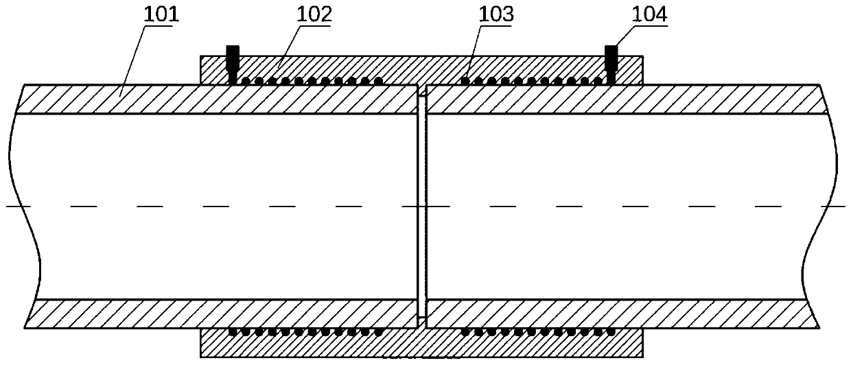
[0051] In this embodiment, an electrofusion pipe fitting with four injection positions is taken as an example. The injection position is set on the end face of the pipe fitting, and the four pouring injection positions are distributed in an array of equal circumferential angles along the axial centerline of the pipe fitting. Chopped carbon fiber reinforced polyethylene composite injection molding electrofusion pipe fittings are used, dispersed chopped carbon fiber is used as the reinforcing fiber, and high-density polyethylene is used as the matrix. The content of the chopped carbon fiber is 10wt%, and the length of the fiber is 6-7mm. In order to make the chopped carbon fiber uniformly dispersed in the high-density polyethylene matrix, the high-density polyethylene is made of powder with a particle size of 32-50 mesh.

[0052] The preparation method of chopped carbon fiber reinforced polyethylene material is carried out according to the following steps:

[0053] (1) The compo...

Embodiment 2

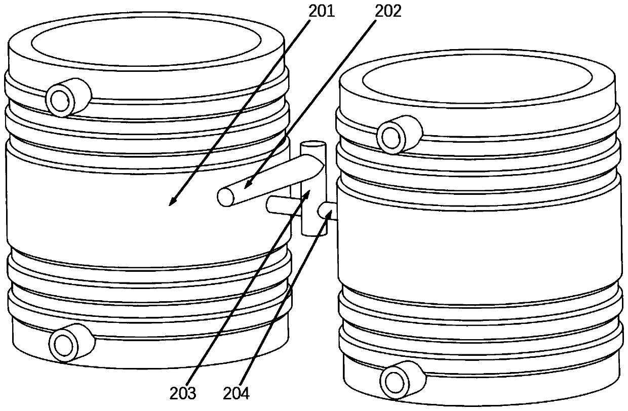
[0061] Such as Figure 5 As shown, the runner system of the short fiber reinforced plastic electrofusion pipe fitting injection mold includes a main runner, four runners and four sprues. In order to facilitate the demoulding of the electrofusion pipe fittings after injection molding, the parting surfaces of the movable mold and the fixed mold of the electrofusion pipe fittings injection mold pass through the axial centerline of the injected electrofusion pipe fittings, and the parting surface is perpendicular to the connection of the injected electrofusion pipe fittings column. In this embodiment, the runner cavity of the injection mold is a cylindrical structure, which is convenient for the part of the runner to be demoulded after injection molding. Half of the runner cylindrical cavity is arranged on the core section, and the other half of the runner cylindrical cavity Arranged on the movable mold and the fixed mold of the injection mold, that is, the end face of the movabl...


PUM

PropertyMeasurementUnit
yield strengthaaaaaaaaaa
lengthaaaaaaaaaa

Abstract

The invention relates to the field of thermoplastic electric melting pipes, and aims to provide a short fiber reinforced plastic electric melting pipe with an optimized injection position and an injection mold thereof. The pipe comprises an electric melting pipe body embedded with a resistance wire, wherein two binding posts which are respectively connected to the two ends of the resistance wire are arranged on the electric melting pipe body; the electric melting pipe body is made of thermoplastic plastic filled with short fibers; and the injection position is arranged on any end face of the electric melting pipe, so that the injection molding direction is parallel to the axial direction of the pipe. According to the short fiber reinforced plastic electric melting pipe, the axial orientation degree of the fibers in the electric melting pipe is improved, the problem that the fiber orientation is not ideal in the short fiber reinforced thermoplastic plastic electric melting pipe which isinjected by the electric melting pipe injection mold is solved, and the axial strength of the short fiber reinforced plastic electric melting pipe is improved. The pipe is formed in one step by an injection molding method, and an additional steel plate or a fiber reinforced layer is not needed, so that the manufacturing process is simple, the stability is good, the process cost is reduced, and the defects of bonding in the prior art, ring-only enhancement and the like are overcome.

Description

technical field [0001] The invention relates to the field of thermoplastic electric fusion pipe fittings, in particular to a short fiber reinforced plastic electric fusion pipe fitting with optimized injection position and an injection mold thereof. Background technique [0002] Non-metallic pipes have the advantages of high flexibility, good toughness, corrosion resistance, and long service life, and the energy consumption of the same volume of production is only 1 / 3 to 1 / 4 of that of steel, which is recognized as a "green" pipe. With the adjustment of my country's energy structure and the acceleration of urbanization, non-metallic pipes are widely used in major national projects. In the field of gas, more than 90% of my country's newly laid medium and low-voltage urban gas pipes use polyethylene pipes; in nuclear power plants In the field of non-metallic pipes, non-metallic pipes have begun to be used for cooling water circulation pipes. At present, the peripheral cooling w...

Claims


Application Information

Patent Timeline
Patent Type & Authority Applications(China)
IPC IPC(8): F16L47/03B29C45/00B29C45/26B29C45/27
CPCB29C45/0005B29C45/261B29C45/2708B29C2045/2709F16L47/03
Inventor 葛周天施建峰倪奉尧孔智勇姚日雾郑津洋
Owner ZHEJIANG UNIV
Why Eureka
Try Eureka