Fuel cell stack and system, fuel cell vehicle and its water management method

A fuel cell stack and fuel cell technology, which is applied in the direction of fuel cells, fuel cell additives, fuel cell heat exchange, etc., can solve the problems of large changes in the structure of the stack, shutdown of the stack due to failure, complex operation, etc., and achieve fast control , prevent downtime failure, and convenient operation

Active Publication Date: 2021-05-11
SHANGHAI SHENLI TECH CO LTD
View PDF9 Cites 0 Cited by
  • Summary
  • Abstract
  • Description
  • Claims
  • Application Information

AI Technical Summary

Problems solved by technology

Taking the second end plate set in the direction of the front of the vehicle, the first end plate as the anode end plate, and the hydrogen inlet, air inlet and cooling water inlet set on the first end plate as an example, when the vehicle goes downhill, the fuel cell stack The anode end plate of the stack is raised, and the lowest single cell voltage in the stack (the lowest single cell is located at figure 2 and Figure 9 The position near the second end plate) decreases sharply over time, eventually leading to the failure of the stack
[0007] In order to solve the problem of flooding, the patent CN 201810515895.0 adopts the scheme of setting up special drainage channels on the hydrogen side and the air side. Gather at the end, but enter the drainage channel and then discharge the stack. However, adding a drainage channel will greatly change the structure of the stack, the operation is complicated and the cost is high, and it cannot solve the problem of rapid drop in the voltage of the single cell when the stack is tilted. question
Patent CN 200680048003.6 estimates the amount of water discharged from the fuel cell based on the state of the fuel cell (remaining water amount or inclination angle), thereby judging the intensity of subsequent purging, and solving the drainage problem by purging, so that the stack can be started normally, although this method It can alleviate the flooding situation, but this method still cannot avoid the problem that the minimum single battery voltage drops sharply due to the flooding of the single battery when the vehicle encounters climbing, descending, and turning situations during operation

Method used


Image

  • Fuel cell stack and system, fuel cell vehicle and its water management method
  • Fuel cell stack and system, fuel cell vehicle and its water management method
  • Fuel cell stack and system, fuel cell vehicle and its water management method

Examples


Embodiment

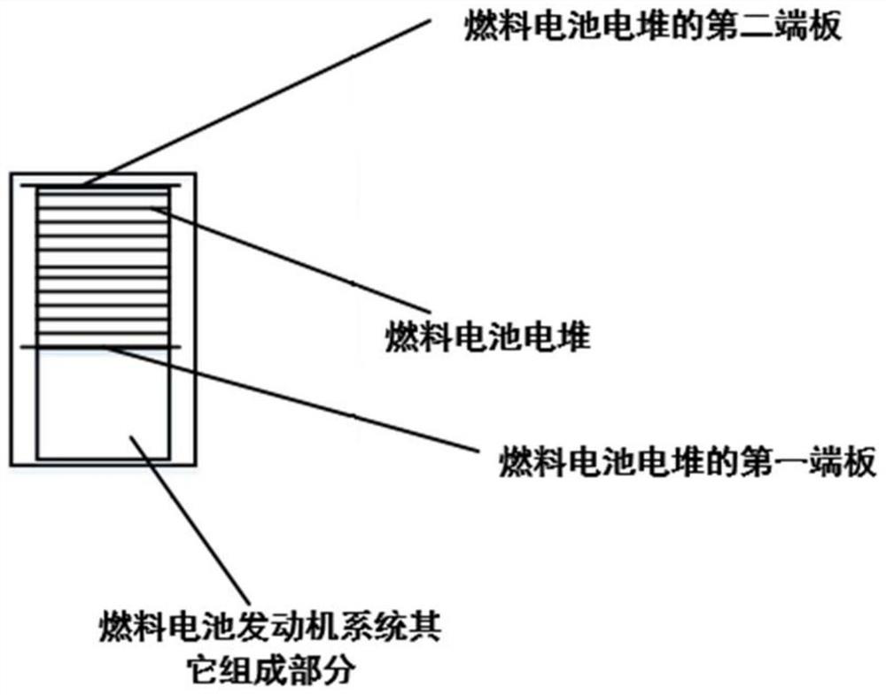
[0039] The invention relates to a fuel cell stack and system, a fuel cell vehicle and a water management method thereof.

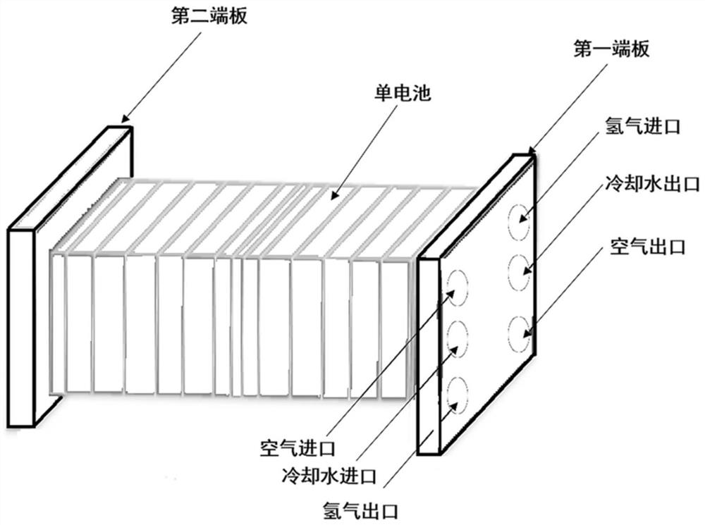
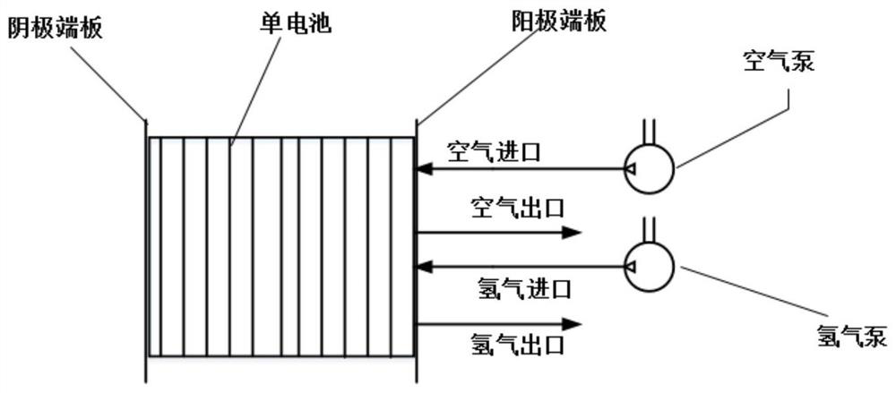
[0040] The first end plate or the second end plate of the fuel cell stack is provided with a hydrogen inlet, an air inlet and a cooling water inlet, as well as a first hydrogen outlet, a second hydrogen outlet, a first air outlet and / or a second air outlet . Wherein, the first hydrogen outlet and the second hydrogen outlet cannot be arranged on the first end plate at the same time, and the first hydrogen outlet and the second hydrogen outlet cannot be arranged on the second end plate at the same time. When the first hydrogen outlet is arranged on the first end plate, the second hydrogen outlet is arranged on the second end plate. Wherein, the first air outlet and the second air outlet cannot be arranged on the first end plate at the same time, and the first air outlet and the second air outlet cannot be arranged on the second end plate at the same time. ...


PUM


Abstract

The invention relates to a fuel cell stack and its system, a fuel cell vehicle and its water management method. The fuel cell stack is provided with a hydrogen inlet, an air inlet, a first hydrogen outlet, a first air outlet, the second end plate is provided with a second hydrogen outlet and / or a second air outlet, the second hydrogen outlet and / or the second air outlet is provided with a solenoid valve, and the solenoid valve is connected to the control system of the fuel cell stack; The above-mentioned fuel cell stack and gyroscope are provided on the fuel cell vehicle; the present invention utilizes the gyroscope to monitor the running status of the vehicle in real time. valve, the hydrogen and / or air outlets on the other side of the end plate are opened to increase drainage and thus avoid flooding of the stack ends. Compared with the prior art, the present invention has the advantages of simple and easy operation, low cost and the like.

Description

technical field [0001] The invention relates to the technical field of fuel cell stacks, in particular to fuel cell stacks and systems, fuel cell vehicles and water management methods thereof. Background technique [0002] Although the industrialization of fuel cell system components has reached a small scale, water management is still a very critical issue, and it has not been fully resolved so far. High-quality water management should achieve a balance between the water content in the membrane, the anode proton electric drag (EOD, electro-osmotic drag) water and the cathode reverse osmosis water, and at least ensure that the reaction gas is not transported to the reaction interface due to liquid water. The obstacles caused by the large fluctuations in performance should also ensure that the proton conduction process does not cause a significant decrease in performance due to water shortage. However, in actual operation, it is difficult to achieve the above two points at t...

Claims


Application Information

Patent Timeline
Patent Type & Authority Patents(China)
IPC IPC(8): H01M8/04007H01M8/04089H01M8/04119H01M8/2465B60L58/30
CPCB60L58/30H01M8/04007H01M8/04089H01M8/04156H01M8/2465Y02E60/50Y02T90/40
Inventor 李骏汤千秋徐鑫甘全全
Owner SHANGHAI SHENLI TECH CO LTD
Why Eureka
Try Eureka