High-voltage cable line operation monitoring system

A high-voltage cable and monitoring system technology, applied in the direction of circuit devices, measuring devices, measuring devices, etc., can solve the problems of cable outer sheath breakdown, delay of emergency remedial time, hazard prediction, etc., and achieve the effect of protecting safety

Inactive Publication Date: 2020-05-01
HANGZHOU JUQI INFORMATION TECH CO LTD
View PDF3 Cites 7 Cited by
  • Summary
  • Abstract
  • Description
  • Claims
  • Application Information

AI Technical Summary

Problems solved by technology

[0002] When the metal sheath of the single-core cable and the cable core pass through the AC current, the magnetic field lines will be hinged, causing a high induced voltage at both ends. Therefore, appropriate grounding measures must be taken to keep the induced voltage within a safe voltage range. , but no matter what grounding method is used, once the grounding system is damaged, such as the crossover interconnection line is stolen or the direct grounding point is not effectively grounded, the outer sheath of the cable will be broken down and the discharge will continue at the breakdown point, causing The temperature of the outer sheath of the cable rises and even causes a fire. In order to ensure the safety of the high-voltage cable operation, it is necessary to monitor the operating status of the high-voltage cable
[0003] At present, the operation monitoring of high-voltage cable lines can only detect the abnormal fault data in the operation of high-voltage cables, and analyze and warn the abnormal fault data. Safety measures are taken in the running state, and the initial location of the abnormal fault data cannot be tracked, so that the monitoring and management personnel cannot find the abnormal fault point of the high-voltage cable at the first time, thus delaying the best emergency remedial time

Method used


Image

  • High-voltage cable line operation monitoring system
  • High-voltage cable line operation monitoring system
  • High-voltage cable line operation monitoring system

Examples


Embodiment Construction

[0065] The following will clearly and completely describe the technical solutions in the embodiments of the present invention with reference to the accompanying drawings in the embodiments of the present invention. Obviously, the described embodiments are only some, not all, embodiments of the present invention.

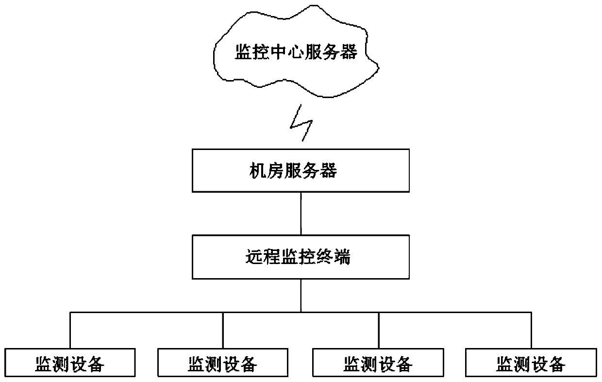
[0066] like Figure 1-Figure 11 As shown, a high-voltage cable line operation monitoring system includes: a monitoring center server, a computer room server, a remote monitoring terminal and monitoring equipment;

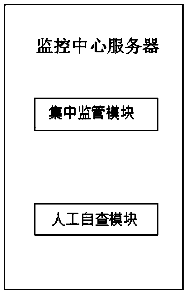
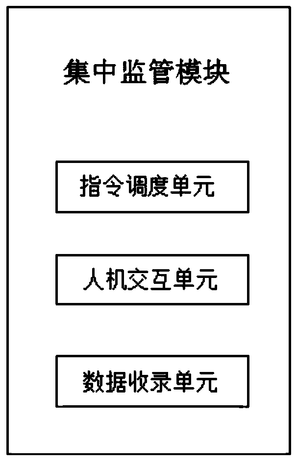
[0067] The monitoring center server is used for centralized monitoring, data analysis, management and real-time control of the multi-state parameters of the subordinate high-voltage cables. Monitoring equipment;

[0068] The server in the computer room is used to receive the data sent by the remote monitoring terminal, and analyze the potential faults of the high-voltage cable through the data, and can also take corresponding control actions and send cont...


PUM


Abstract

The invention discloses a high-voltage cable line operation monitoring system, which is characterized by comprising a monitoring center server, a machine room server, a remote monitoring terminal andmonitoring equipment, wherein the monitoring center server is used for carrying out centralized monitoring, data analysis, management and real-time control on multi-state parameters of operation of subordinate high-voltage cables; the machine room server is used for receiving data sent by the remote monitoring terminal; the remote monitoring terminal is used for receiving high-voltage cable stateparameters of each measurement point in real time; and the monitoring equipment is a grounding current transmitter and is used for collecting circulation data parameters of high-voltage current. The high-voltage cable line operation monitoring system can timely and accurately monitor circulation abnormal data information occurring in high-voltage cable operation, performs simulation modeling on abnormal data in combination with virtual modeling, predicts possible fault influences of the abnormal data on the high-voltage cable operation, and protects the safety of the high-voltage cable line operation.

Description

technical field [0001] The invention relates to the technical field of high-voltage cable operation monitoring, in particular to a high-voltage cable line operation monitoring system. Background technique [0002] When the metal sheath of a single-core cable and the cable core pass through an alternating current, the magnetic force lines will be hinged, causing a high induced voltage at both ends. Therefore, appropriate grounding measures must be taken to keep the induced voltage within a safe voltage range. , but no matter what grounding method is used, once the grounding system is damaged, such as the cross interconnection line is stolen or the direct grounding point is not effectively grounded, the outer sheath of the cable will be broken down and the discharge will continue at the breakdown point, causing The temperature of the outer sheath of the cable rises and even causes a fire. In order to ensure the safety of the high-voltage cable operation, it is necessary to mon...

Claims


Application Information

Patent Timeline
Patent Type & Authority Applications(China)
IPC IPC(8): H02J13/00G01R31/00
CPCG01R31/00
Inventor 倪晓璐裘明松周铭权孟庆铭董琪郭能俊周杰陈荣鑫
Owner HANGZHOU JUQI INFORMATION TECH CO LTD
Why Eureka
Try Eureka