Harvesting machine and harvesting platform thereof

A harvester and header technology, which is applied to harvesters, cutters, agricultural machinery and implements, etc., can solve the problems of complex structure and large size of the header, and achieve the purpose of reducing the size of the header, simplifying the structure, and reducing harvest losses. Effect

Inactive Publication Date: 2020-05-05
HENAN UNIV OF SCI & TECH
View PDF8 Cites 2 Cited by
  • Summary
  • Abstract
  • Description
  • Claims
  • Application Information

AI Technical Summary

Problems solved by technology

[0003] The purpose of the present invention is to provide a harvester to solve the problems of complex structure and large volume of the header of the harvester in the prior art; meanwhile, a harvester header with a simple structure and small volume is provided

Method used


Image

  • Harvesting machine and harvesting platform thereof
  • Harvesting machine and harvesting platform thereof
  • Harvesting machine and harvesting platform thereof

Examples


specific Embodiment 1

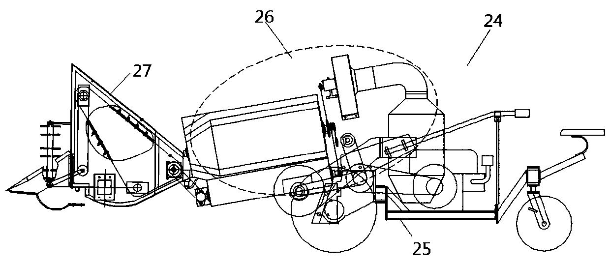
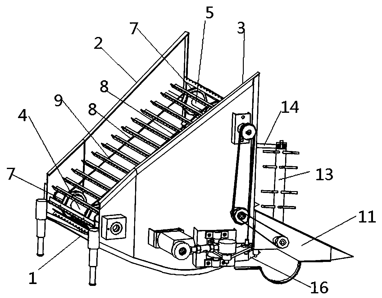
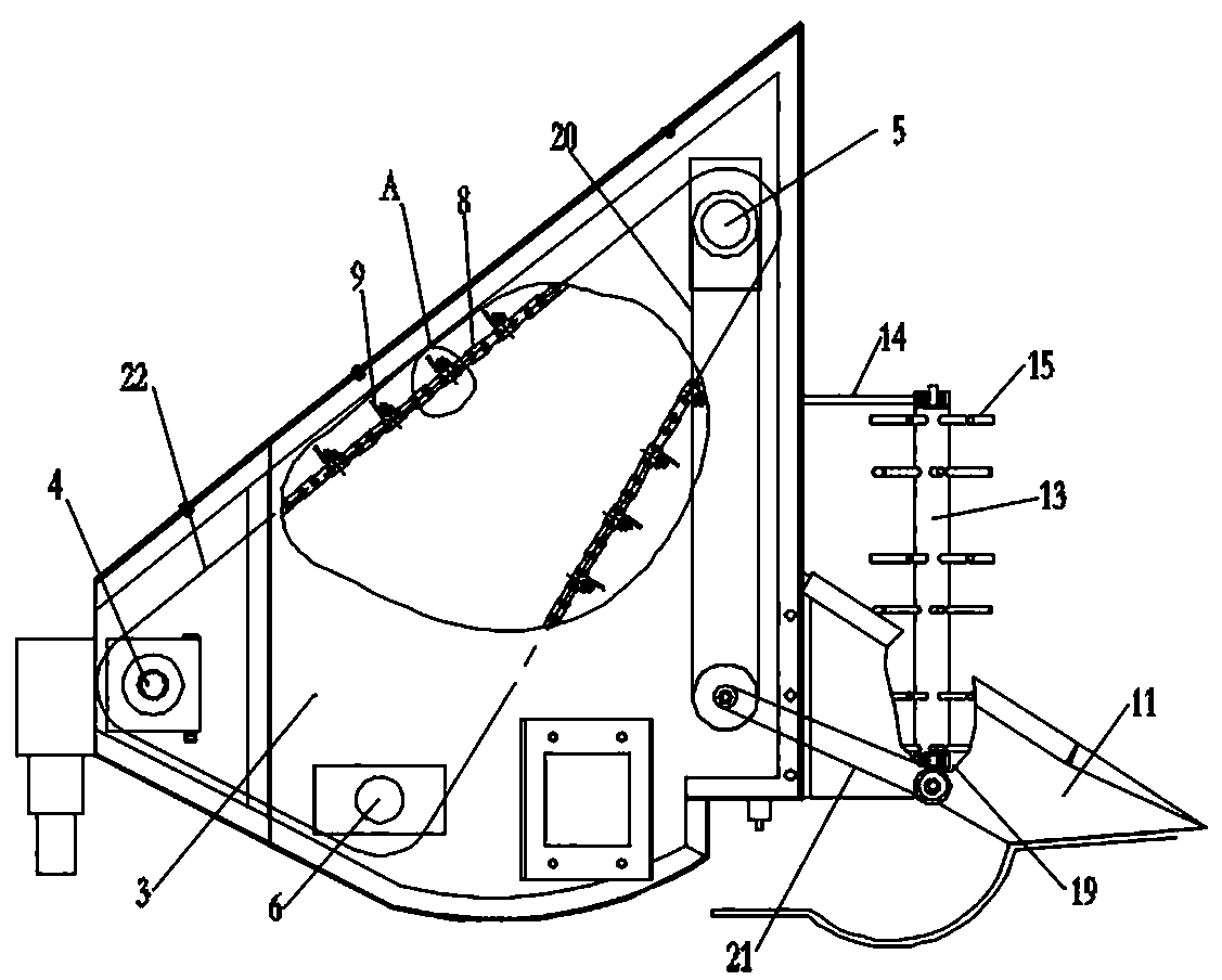
[0058] Such as figure 1 Shown is the overall structure diagram of the harvester 24, the harvester 24 includes a walkable harvester frame 25 and a threshing and cleaning system 26 arranged on the harvester frame 25, and also includes a The harvester header 27, the harvester 24 is also provided with a driving device that drives the harvester header 27 work; as Figure 2-3 As shown, the specific structure of the harvester header 27 is shown, and the harvester header 27 includes a support housing with a bottom support wall 1, a left support wall 2 and a right support wall 3, and the left support wall 2 and the right support wall 3 It is arranged on the bottom support wall 1 at intervals along the left and right sides, and the lower part of the harvester header 27 front side is provided with a cutter assembly 16, and the cutter assembly 16 is used for crop stubble cutting.

[0059] On the lower side of the rear end of the support housing, there is a drive shaft 4 that is rotatably...

specific Embodiment 5

[0069] The specific embodiment 5 of the harvester of the present invention differs from embodiment 1 in that the flexible scraping strip is a long strip with a rectangular cross section. Bolts on the side walls of the tank are fixed to the flexible scraping strips. Such setting simplifies the structure of the flexible scraping strip as a consumable part, reduces its manufacturing cost, and facilitates low-cost replacement of the flexible scraping strip in the later stage.

[0070] In other embodiments, in other embodiments, a separate motor can be used to drive the auxiliary reel roller. At this time, there is no need to set the reversing gear set and the transmission structure between the upper transmission shaft, and directly make the output shaft of the motor and the auxiliary reel roller Wo roller transmission connection; in other embodiments, the first transmission wheel is arranged on the driving shaft, and the second transmission wheel is arranged at the upper middle po...

specific Embodiment

[0073] The specific embodiment of the harvester header of the present invention: the specific structure of the harvester header is the same as the structure of the harvester header adopted in the above-mentioned harvester embodiment, and will not be repeated.


PUM


Abstract

The invention relates to a harvesting machine and a harvesting platform thereof. The harvesting platform includes a supporting shell having a bottom support wall, a left support wall and a right support wall, a cutter assembly and a crop-pulling transportation mechanism; the crop-pulling transportation mechanism includes a driving shaft located on the lower side on the rear end of the supporting shell and an upper transmission shaft located on the upper side on the front end of the supporting shell; the driving shaft and the upper transmission shaft are rotatably installed on the left and right support walls; annular traction elements having poking members are wound on the driving shaft and the upper transmission shaft in a transmission manner; and when the annular traction elements move,the parts, close to the cutter assembly, of the annular traction elements are used for poking crops into the shell, and the parts, away from the cutter assembly, of the annular traction elements are used for backward poking and transporting the crops to the device, located on the rear side of the harvesting platform of the harvesting machine, of the harvesting machine. The front sides of the annular traction elements can achieve the effects of poking the crops, and the rear sides of the annular traction elements can achieve transportation effects; and through the combination of the functions of crop-poking wheels and conveying devices in traditional harvesting platforms of harvesting machines, the structure of the harvesting platform of the harvesting machine can be simplified, and the size of the harvesting platform of the harvesting machine can be reduced.

Description

technical field [0001] The invention relates to a harvester and its header, belonging to the field of crop cycle harvesting. Background technique [0002] Along with the continuous improvement of the level of my country's agricultural mechanization, crops such as rice, wheat, soybean and cabbage seeds have basically realized mechanized harvesting. As the utility model with the authorized announcement number 209489160U, a harvester is disclosed. The reel and auger device, after the cutter cuts the crops, the rotating reel feeds the crops into the shell of the header, and then the auger at the rear of the header as a conveying device feeds the crops Conveys to the follow-up unit of the harvester behind the header. In this harvester in the prior art, its header realizes reeling and transportation respectively through the independent reel and auger device, which causes the header to have a complex structure and a large volume. Contents of the invention [0003] The purpose of ...

Claims


Application Information

Patent Timeline
Patent Type & Authority Applications(China)
IPC IPC(8): A01D41/02A01D41/06A01D41/14A01D57/01A01D57/02
CPCA01D41/02A01D41/06A01D41/14A01D57/02A01D57/01
Inventor 王升升周浩解晓琳陈盼卢梦晴胡金鹏李路超刘浩恒
Owner HENAN UNIV OF SCI & TECH
Why Eureka
Try Eureka