Selection of measuring coils in magnetic resonance imaging and magnetic resonance facility

A technology of magnetic resonance imaging and measuring coils, which is applied in the directions of magnetic resonance measurement, magnetic variable measurement, magnetic performance measurement, etc., can solve the problems of error-prone, impaired availability of MR facilities, time-consuming, etc., and achieve the effect of reducing artifacts

Pending Publication Date: 2020-05-05
SIEMENS HEALTHCARE GMBH
View PDF0 Cites 0 Cited by
  • Summary
  • Abstract
  • Description
  • Claims
  • Application Information

AI Technical Summary

Problems solved by technology

However, this then does not take into account possible characteristics resulting from the use of different coils, different types of support, variations due to the patient's shape, etc.
Furthermore, performing a manual selection of coils is time-consuming and error-prone, compromising the availability of the MR facility

Method used


Image

  • Selection of measuring coils in magnetic resonance imaging and magnetic resonance facility
  • Selection of measuring coils in magnetic resonance imaging and magnetic resonance facility
  • Selection of measuring coils in magnetic resonance imaging and magnetic resonance facility

Examples


Embodiment Construction

[0025] The above-described characteristics, features and advantages of the present invention, as well as the manner and method of achieving these characteristics, characteristics and advantages, become clear and clearly understood in conjunction with the following description of the embodiments, which in conjunction with the accompanying The figure elaborates.

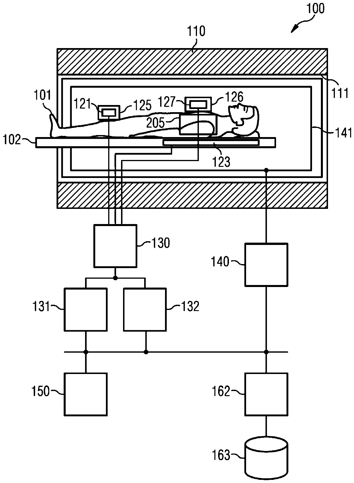
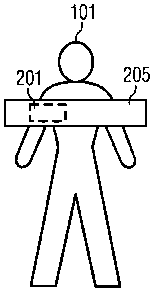
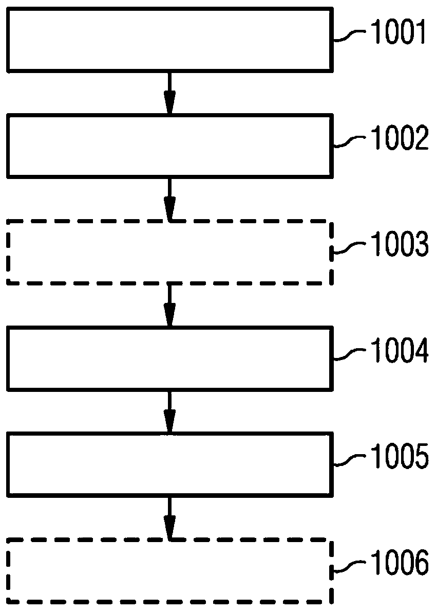
[0026] Hereinafter, the present invention will be described in detail based on preferred embodiments with reference to the accompanying drawings. In the drawings, the same reference numerals designate the same or similar elements. The drawings are schematic representations of different embodiments of the invention. Elements shown in the figures are not necessarily shown to scale. Rather, the different elements shown in the figures are depicted such that their functions and general purposes are understandable to those skilled in the art. The connections and couplings shown in the figures between functional units and ...


PUM


Abstract

The present disclosure relates to techniques for the selection of one or more measuring coils in magnetic resonance imaging. Herein, account can be taken of a preselection in the selection of the oneor more measuring coils from a plurality of candidate coils.

Description

technical field [0001] Various examples of the invention relate to techniques for selecting one or more measurement coils in magnetic resonance imaging. Background technique [0002] In magnetic resonance (MR) imaging different anatomical regions of the person being examined can be examined. For this purpose, the nuclear spins can be deflected away from the rest position in the examination region by injecting high-frequency (HF) pulses. Raw data corresponding to the RF signal of the relaxed nuclear spins can then be detected. One or more MR images can be generated therefrom. Measuring coils are used for transmitting and receiving RF signals. [0003] The operation of an MR facility typically requires the setting of a large number of operating parameters. For example, one or more MR protocols must be selected, which define the sequence of the injected RF pulses and the duration for receiving the RF signals, as well as other parameters such as, for example, gradient pulses...

Claims


Application Information

Patent Timeline
IPC IPC(8): A61B5/055G01R33/20G01R33/34
CPCA61B5/055G01R33/34G01R33/20G01R33/3664G01R33/546G01R33/36G01R33/385G01R33/3875
Inventor 斯特凡·迈尔曼努埃拉·里克
Owner SIEMENS HEALTHCARE GMBH
Why Eureka
Try Eureka