
A Low Frequency Vibration Isolation Superstructure

A superstructure and vibration isolation technology, applied in vibration suppression adjustment, spring/shock absorber, mechanical equipment, etc., can solve the problems of narrow operating frequency band, neglect of static load engineering requirements, etc., achieve a wide vibration isolation frequency range, shorten development Period and good vibration isolation effect

Active Publication Date: 2021-08-17
BEIJING INSTITUTE OF TECHNOLOGYGY
View PDF0 Cites 0 Cited by
  • Summary
  • Abstract
  • Description
  • Claims
  • Application Information

AI Technical Summary

Problems solved by technology

However, the current superstructure design mainly considers the dynamic performance, the working frequency band is narrow, and the static load-bearing and lightweight engineering requirements are often ignored.

Method used


Image

  • A Low Frequency Vibration Isolation Superstructure
  • A Low Frequency Vibration Isolation Superstructure
  • A Low Frequency Vibration Isolation Superstructure

Examples


Embodiment 1

[0049] The rated load of the CMG equipment of a certain type of satellite is 160N. The bottom size of the CMG equipment is a circle with a radius of 111mm. The frequency is concentrated at 50Hz, 100Hz, 160Hz and 200Hz; at the same time, the device will also generate linear vibration in X and Z directions and angular vibration in X, Y and Z directions. The design goal is to make the superstructure able to carry the rated load while well isolating the linear vibration above 30Hz in the Y direction of the equipment, and at the same time have a certain suppression effect on other forms of vibration of the equipment.

[0050] According to the design and manufacture method of the low-frequency vibration-isolation superstructure, the following design scheme is selected: select the future 8000 type photosensitive resin of the Shenzhen Future Factory as the base material of the low-frequency vibration-isolation superstructure, with an elastic modulus of 1400MPa and a density of 1131kg / m...

Embodiment 2

[0053] The rated load of a certain vibration source equipment is 2800N, and the main vibration form during operation is the linear vibration in the Y direction (perpendicular to the direction of the upper mounting panel). The main frequencies of this form of vibration are concentrated at 15Hz, 23Hz and 60Hz; The equipment also produces linear vibrations in X, Z directions and angular vibrations in X, Y, Z directions. The design goal is to make the superstructure able to carry the rated load while well isolating the linear vibration above 10Hz in the Y direction of the equipment, and at the same time have a certain suppression effect on other forms of vibration of the equipment.

[0054] According to the design and manufacture method of the low-frequency vibration-isolation superstructure, the following design scheme is selected: AlSi10Mg alloy is selected as the base material of the low-frequency vibration-isolation superstructure, with an elastic modulus of 80GPa and a density...


PUM


Abstract

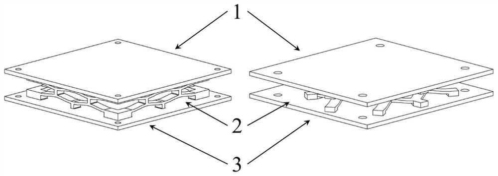
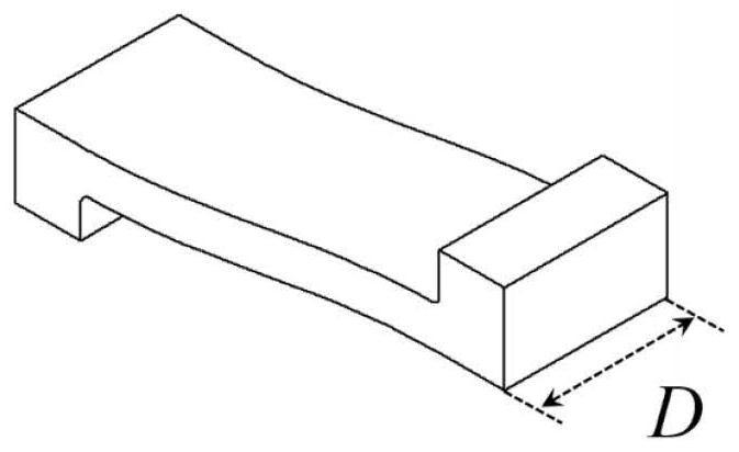
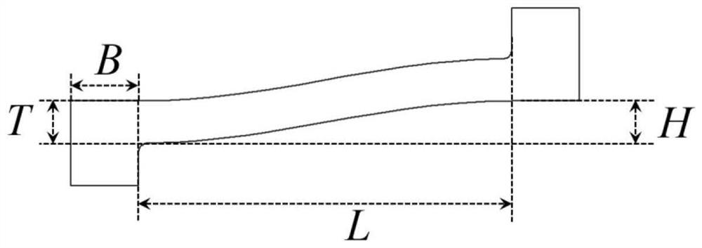
The invention relates to a low-frequency vibration isolation superstructure, which belongs to the technical field of superstructure vibration isolation. The superstructure of the present invention includes an upper mounting panel, a lower mounting panel and a vibration isolation functional structure. The vibration isolation functional structure is formed by periodic arrangement and combination of supercells. A sinusoidal curved beam, one end of the curved beam is processed with a vertically downward restraining protrusion, and the other end of the curved beam is processed with a vertically upward connecting protrusion, which is formed by rotating with the connecting protrusion as the rotation center. A supercell in which the above unit cells are symmetrically distributed. The superstructure of the present invention can well isolate the linear vibration in the main bearing direction while being able to carry the weight of the equipment itself, and has a certain isolation effect on the linear vibration in other directions and the angular vibration in three directions; the superstructure The structure has the advantages of simple structure, light weight, easy preparation, convenient installation and wide application range.

Description

technical field [0001] The invention relates to a low-frequency vibration isolation superstructure, which belongs to the technical field of superstructure vibration isolation. Background technique [0002] As the requirements for light weight and high performance of major equipment represented by spacecraft continue to increase, more stringent requirements are put forward for the static load and vibration isolation capabilities of lightweight structures. On the other hand, the low-frequency, micro-amplitude, and complex forms of vibration generated by engineering equipment also pose a greater challenge to the design of vibration isolation devices. For example, in the aerospace field, the inertial actuator (CMG) of satellites will Low-frequency micro-vibrations in six directions (translation and rotation in the three directions of X, Y, and Z) are generated, which seriously affect key performances such as imaging accuracy and service life of the satellite. [0003] Tradition...

Claims


Application Information

Patent Timeline
Patent Type & Authority Patents(China)
IPC IPC(8): F16F15/00
CPCF16F15/00
Inventor 朱睿赵伟佳王倚天赵建雷
Owner BEIJING INSTITUTE OF TECHNOLOGYGY
Learn More