
Gas waste heat recovery device

A waste heat recovery and gas technology, applied in the direction of heat exchangers, heat exchanger types, indirect heat exchangers, etc., can solve problems such as dust accumulation, slagging, reducing heat exchange efficiency, and affecting safe and reliable operation of equipment to achieve heat exchange The effect of increasing the area, reducing the size of the equipment, and avoiding the phenomenon of ash slagging in the heating area

Pending Publication Date: 2020-05-05
CHANGZHENG ENG
View PDF0 Cites 1 Cited by
  • Summary
  • Abstract
  • Description
  • Claims
  • Application Information

AI Technical Summary

Problems solved by technology

However, because the high-temperature crude syngas produced by coal gasification usually entrains molten ash into the waste heat recovery device, it is easy to cause problems such as ash accumulation and slagging, thereby reducing the heat exchange efficiency and affecting the safe and reliable operation of the equipment.

Method used


Image

  • Gas waste heat recovery device
  • Gas waste heat recovery device

Examples


Embodiment Construction

[0015] Specific embodiments of the present invention will be described in detail below with reference to the accompanying drawings.

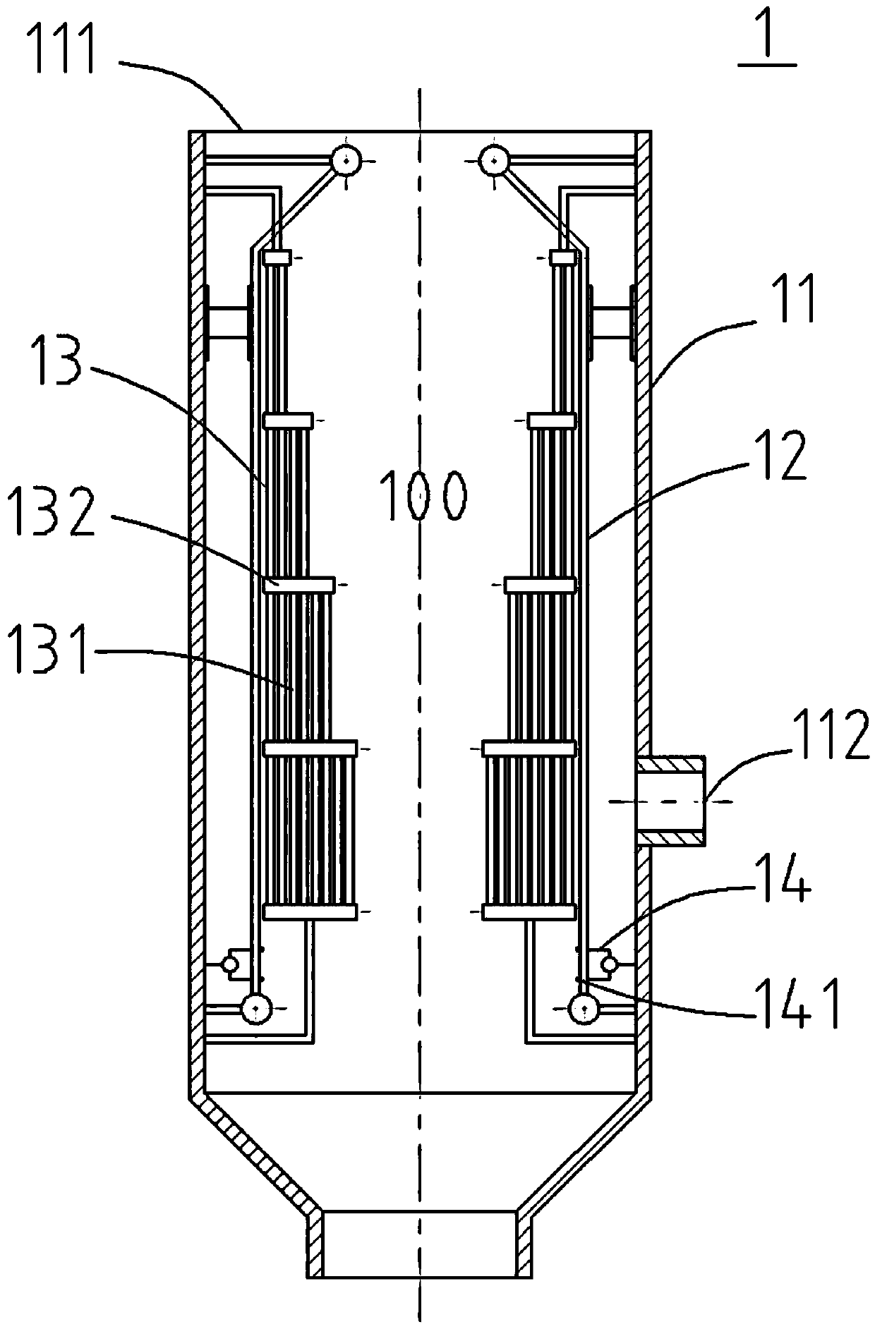
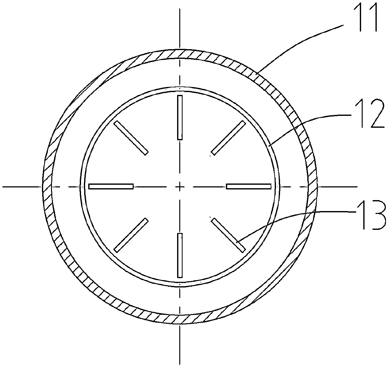
[0016] Such as figure 1 and 2 As shown, the gas waste heat recovery device 1 of the present invention includes: a cylindrical pressure-bearing shell 11, the upper part of the pressure-bearing shell 11 is provided with an air inlet 111, and the lower part is provided with an air outlet 112, and the air inlet 111 is used for The high-temperature crude synthesis gas enters, and the gas outlet 112 is used to discharge the gas after waste heat recovery.

[0017] A circumferential water-cooled wall 12 is arranged inside the pressure-bearing shell 11, and the circumferential water-cooled wall 12 is coaxially arranged with the pressure-bearing shell 11, and a gas circulation channel extending from top to bottom is formed in the circumferential water-cooled wall 12 100, the gas circulation channel 100 is provided with several panel-type water-cooled wa...


PUM


Abstract

The invention discloses a gas waste heat recovery device. The gas waste heat recovery device comprises a cylindrical pressure-bearing shell, a gas inlet is formed in the upper portion of the pressure-bearing shell, a gas outlet is formed in the lower portion of the pressure-bearing shell, the pressure-bearing shell is internally provided with a circumferential water cooling wall, a gas flow channel which extends from top to bottom is formed in the circumferential water cooling wall, the gas flow channel is internally provided with a plurality of screen group type water cooling walls, each screen group type water cooling wall is formed by sequentially connecting a plurality of screen type water cooling walls through a middle header from top to bottom, the widths of the plurality of screen type water cooling walls which form the screen group type water cooling walls are sequentially increased from top to bottom; and a water chilling device is arranged at the lower end of the circumferential water cooling wall. According to the gas waste heat recovery device, the ash deposition and slagging phenomena of the water cooling wall caused by molten-state ash carried by high-temperature gascan be effectively avoided, the heat exchange efficiency per unit volume is improved, and the device size is reduced.

Description

technical field [0001] The invention relates to a waste heat recovery device, in particular to a gas waste heat recovery device for recovering the waste heat of high-temperature crude synthesis gas produced by a coal gasification furnace. Background technique [0002] The waste heat recovery device is the key equipment for sensible heat recovery in the energy and chemical industry, especially for sensible heat recovery of high-temperature and high-pressure crude synthesis gas produced by coal gasification, which can improve the energy utilization efficiency of the system. Normally, the waste heat recovery device used for sensible heat recovery is directly connected to the coal gasifier, and the high-temperature crude syngas enters the waste heat recovery device, and realizes sensible heat recovery through heat exchange, thereby reducing the temperature of the crude synthesis gas, and finally discharges the waste heat for recovery into downstream process equipment. However, ...

Claims


Application Information

Patent Timeline
Patent Type & Authority Applications(China)
IPC IPC(8): F28D7/16F28F1/22F28D21/00F28C1/00
CPCF28D7/16F28F1/22F28D21/0003F28C1/003
Inventor 梁军辉郭进军李晓飞姜从斌丁建平李振祥陈永进
Owner CHANGZHENG ENG
Learn More