Urea box fault diagnosis method and device, vehicle and storage medium
A fault diagnosis and urea tank technology, applied in the field of vehicle and storage medium, urea tank fault diagnosis, can solve problems affecting the vehicle emission performance urea tank temperature control accuracy, inability to monitor the real availability of the urea tank temperature sensor in real time, and urea state estimation errors and other problems, so as to avoid errors in urea state estimation or excessive heating time.
- Summary
- Abstract
- Description
- Claims
- Application Information
AI Technical Summary
Problems solved by technology
Method used
Image
Examples
Embodiment 1
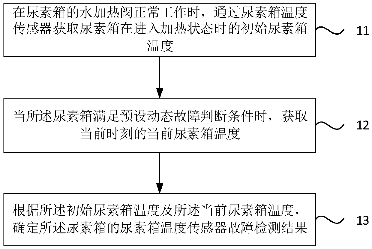
[0030] figure 1 It is a flow chart of a urea solution tank fault diagnosis method provided by Embodiment 1 of the present invention. This embodiment is applicable to the situation of dynamic diagnosis of a urea solution tank temperature sensor fault, and the method can be executed by a urea solution tank fault diagnosis device. The urea solution tank The fault diagnosis device can be implemented by software and / or hardware, and the urea tank fault diagnosis device can be configured on a computing device, specifically including the following steps:
[0031] Step 11. When the water heating valve of the urea tank is working normally, obtain the initial urea tank temperature when the urea tank enters the heating state through the urea tank temperature sensor.
[0032] Wherein, the water heating valve of the urea tank can be understood as a solenoid valve used to control the thawing and heating of the urea solution in the urea tank to prevent urea crystallization.
[0033] Specifi...
Embodiment 2
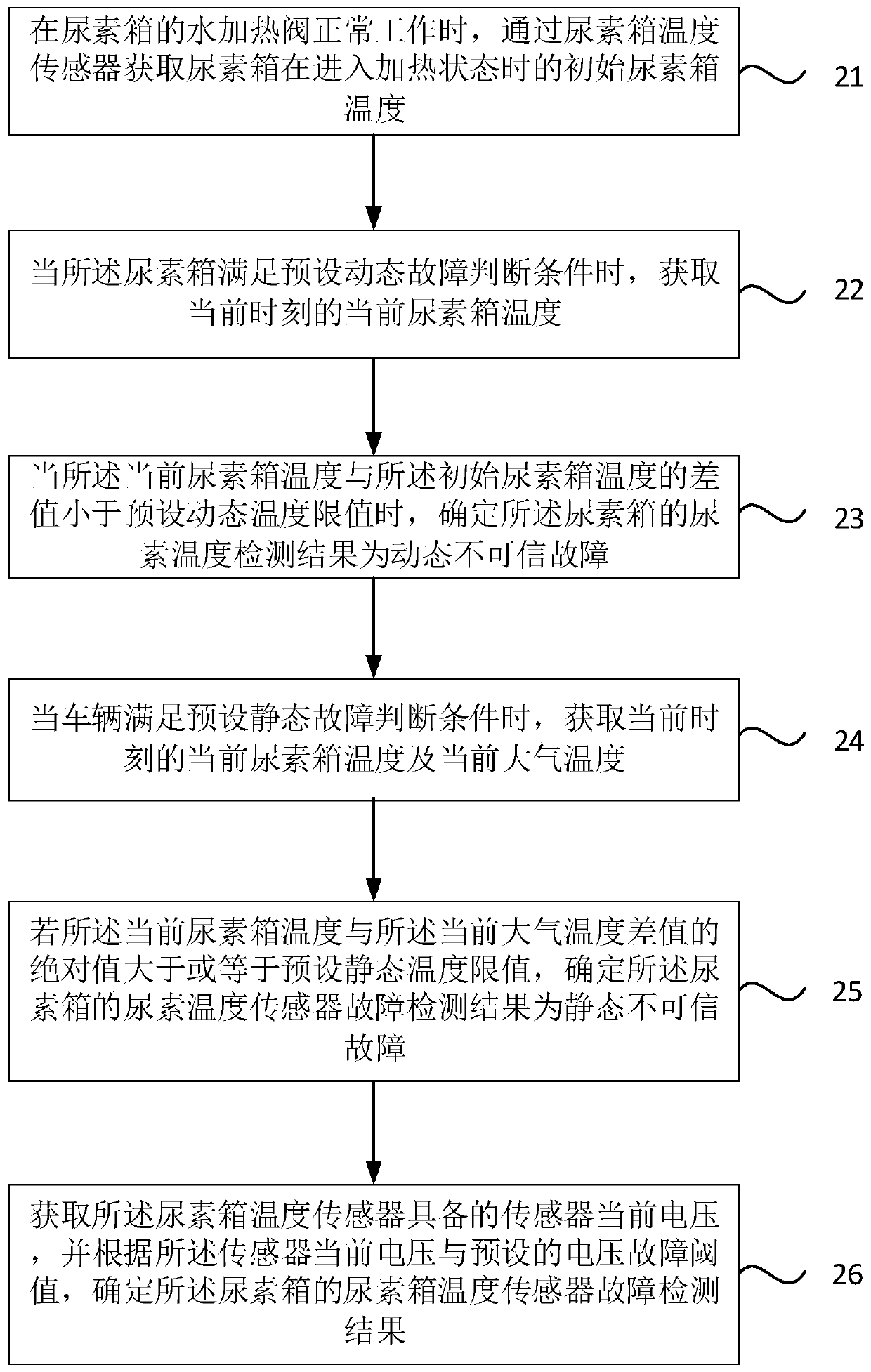
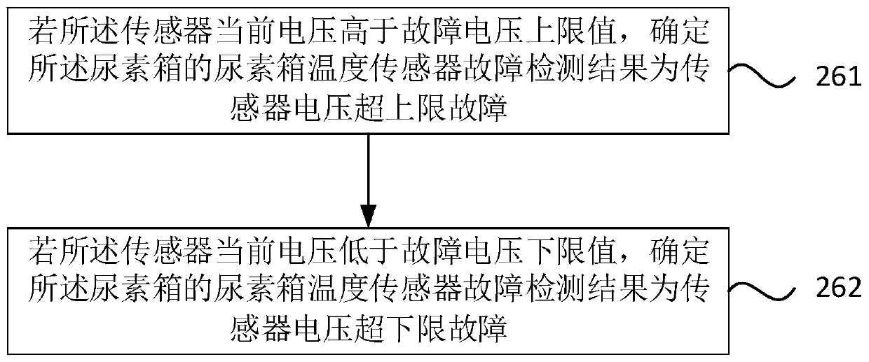
[0042] figure 2 It is a flow chart of a urea tank fault diagnosis method provided by Embodiment 2 of the present invention. The technical solution of this embodiment is further refined on the basis of the above-mentioned technical solution, specifically including the following steps:
[0043] Step 21. When the water heating valve of the urea tank is working normally, obtain the initial urea tank temperature when the urea tank enters the heating state through the urea tank temperature sensor.
[0044] Step 22, when the urea solution tank satisfies the preset dynamic fault judgment condition, acquire the current temperature of the urea solution tank at the current moment.
[0045]Step 23: When the difference between the current urea tank temperature and the initial urea tank temperature is less than a preset dynamic temperature limit, determine that the urea temperature detection result of the urea tank is a dynamic unreliable fault.
[0046] Among them, the dynamic unreliabl...
Embodiment 3
[0070] Figure 5 A structural diagram of a urea tank fault diagnosis device provided in Embodiment 3 of the present invention, the urea tank fault diagnosis device includes: an initial temperature acquisition module 31 , a current temperature acquisition module 32 and a detection result determination module 33 .
[0071] Wherein, the initial temperature acquiring module 31 ' is used to obtain the initial urea tank temperature when the urea tank enters the heating state through the urea tank temperature sensor when the water heating valve of the urea tank is working normally; the current temperature acquiring module 32 is used for when When the urea tank satisfies the preset dynamic fault judgment condition, obtain the current temperature of the urea tank at the current moment; the detection result determination module 33 is used to determine the urea tank according to the initial urea tank temperature and the current urea tank temperature The fault detection result of the urea...
PUM
 Abstract
Description
Claims
Application Information
 - R&D
- Intellectual Property
- Life Sciences
- Materials
- Tech Scout
- Unparalleled Data Quality
- Higher Quality Content
- 60% Fewer Hallucinations
Browse by: Latest US Patents, China's latest patents, Technical Efficacy Thesaurus, Application Domain, Technology Topic, Popular Technical Reports.
© 2025 PatSnap. All rights reserved.Legal|Privacy policy|Modern Slavery Act Transparency Statement|Sitemap|About US| Contact US: help@patsnap.com


