Integrated inspection bench for control system

A control system and inspection platform technology, applied in the field of inspection platform, can solve problems such as poor reliability and low efficiency, and achieve the effect of avoiding blind spots and increasing inspection efficiency

Inactive Publication Date: 2020-05-08
XIAN HUIFU RONGTONG INFORMATION TECH CO LTD
View PDF3 Cites 8 Cited by
  • Summary
  • Abstract
  • Description
  • Claims
  • Application Information

AI Technical Summary

Problems solved by technology

[0004] The purpose of the present invention is to provide a control system integration inspection platform to solve the problem that when the inspection work in the above-mentioned background technology adopts a manual form for preliminary inspection of the appearance of the system integration, there are visual blind spots when the naked eye can only observe, and two people are required to cooperate. In order to carry out inspection, the problem of low efficiency and poor reliability

Method used


Image

  • Integrated inspection bench for control system
  • Integrated inspection bench for control system
  • Integrated inspection bench for control system

Examples


Embodiment 1

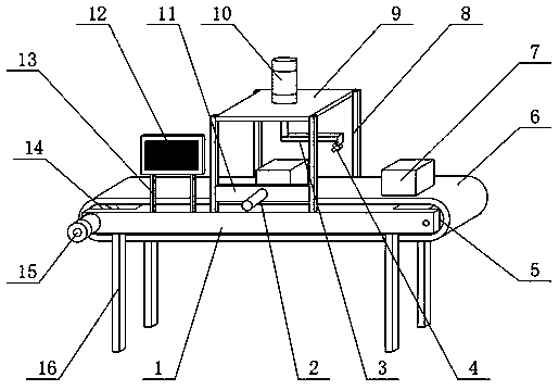
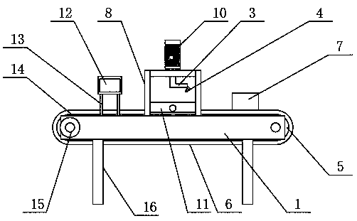
[0020] see Figure 1-3 , the present invention provides a technical solution for a control system integrated inspection platform: it includes an inspection platform body 1, and the two sides of the inspection platform body 1 are respectively rotatably connected with a driving roller 14 and a driven roller 5, and the driving roller 14 and the driven roller 5 They are connected by a transmission belt 6, and the front of the test bench body 1 is equipped with a second motor 15, the output shaft of the second motor 15 is connected to the drive roller 14 by transmission, and the top of the test bench body 1 is fixedly connected with four poles 8, The tops of the four poles 8 are fixedly connected with a support 9, the top of the support 9 is equipped with a first motor 10, the output end of the first motor 10 is connected with a support 3, and the end of the support 3 is equipped with a camera 4, a conveyor belt The top of 6 is provided with a system integration 7, and the system i...

Embodiment 2

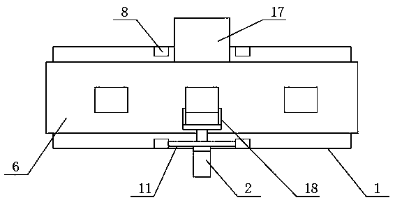
[0022] On the basis of embodiment one, refer to figure 2 to combine image 3 , wherein two poles 8 are fixedly connected with a side plate 11, the front of the side plate 11 is equipped with a cylinder 2, the telescopic end of the cylinder 2 is fixedly connected with a push plate 18, and the other two poles 8 are fixedly connected with a support plate 17, two Each support plate 17 is equal to the conveyor belt 6. When the present invention detects unqualified products, the cylinder 2 pushes the system integration 7 to the support plate 17 through the push plate 18, thereby separating unqualified products and qualified products in time. , qualified products are conveyed to the left through conveyor belt 6.

[0023] During specific use, the present invention is a control system integrated inspection platform. When the present invention is inspected, the system is integrated and placed on the right end of the conveyor belt 6. At this time, the second motor 15 drives the conveyo...


PUM


Abstract

The invention discloses an integrated inspection bench for a control system. The integrated inspection bench for the control system comprises an inspection bench body; two sides of the inspection bench body are respectively and rotatably connected with a driving roller and a driven roller; the driving roller is in transmission connection with the driven roller through a conveying belt; a second motor is mounted on the front surface of the inspection bench body; and an output shaft of the second motor is in transmission connection with the driving roller. When the integrated inspection bench for the control system performs inspection, a system integration is placed at the right end of the conveying belt, at the moment, the conveying belt drives the system integration to move to the positionbelow a supporting seat, and at the moment, a first motor drives a camera to rotate through the bracket; four side surfaces of the system integration are photographed after the camera surrounds the system integration for a circle; images are displayed through a display screen, so that a blind area is avoided; meanwhile, the inspection efficiency is improved; at the moment, the system integrationis pushed to the supporting plate by an air cylinder through a pushing plate, so that unqualified products are separated from qualified products; and the qualified products are conveyed to the left side through the conveying belt.

Description

technical field [0001] The invention relates to a test bench, in particular to a control system integrated test bench. Background technique [0002] System integration often refers to the business of combining software, hardware and communication technology to solve information processing problems for users. The separate parts of the integration are originally independent systems. After the integration, the parts of the whole can be organically integrated with each other. Work in a coordinated manner to give full play to the overall benefits and achieve the goal of overall optimization. [0003] In response to this, Chinese Patent No. CN110118777A proposes a control system system integration intelligent inspection; Chinese Patent No. CN110347682A proposes a large data storage system integration system; Chinese Patent No. CN110187648A proposes an aircraft radio system integrated simulation simulation test system, However, when the mounting bracket of the above-mentioned pate...

Claims


Application Information

Patent Timeline
Patent Type & Authority Applications(China)
IPC IPC(8): B07C5/34B07C5/36B07C5/38B07C5/02G01N21/84
CPCB07C5/02B07C5/34B07C5/361B07C5/38G01N21/84
Inventor 赵航
Owner XIAN HUIFU RONGTONG INFORMATION TECH CO LTD
Why Eureka
Try Eureka