Numerical control metal cutting machine tool

A metal cutting and machine tool technology, applied in the field of mechanical parts processing, can solve problems such as friction heating, affecting metal cutting work, etc.

Active Publication Date: 2020-05-08
江苏中智自动化股份有限公司
View PDF7 Cites 3 Cited by
  • Summary
  • Abstract
  • Description
  • Claims
  • Application Information

AI Technical Summary

Problems solved by technology

[0004] Aiming at the deficiencies in the prior art, the purpose of the present invention is to provide a numerically controlled metal cutting machine tool to solve the problem that there are a large amount of metal shavings on the surface of t...

Method used


Image

  • Numerical control metal cutting machine tool
  • Numerical control metal cutting machine tool
  • Numerical control metal cutting machine tool

Examples


no. 1 example

[0029] Such as Figure 1-Figure 5 As shown, the present invention provides a technical scheme of a numerically controlled metal cutting machine tool:

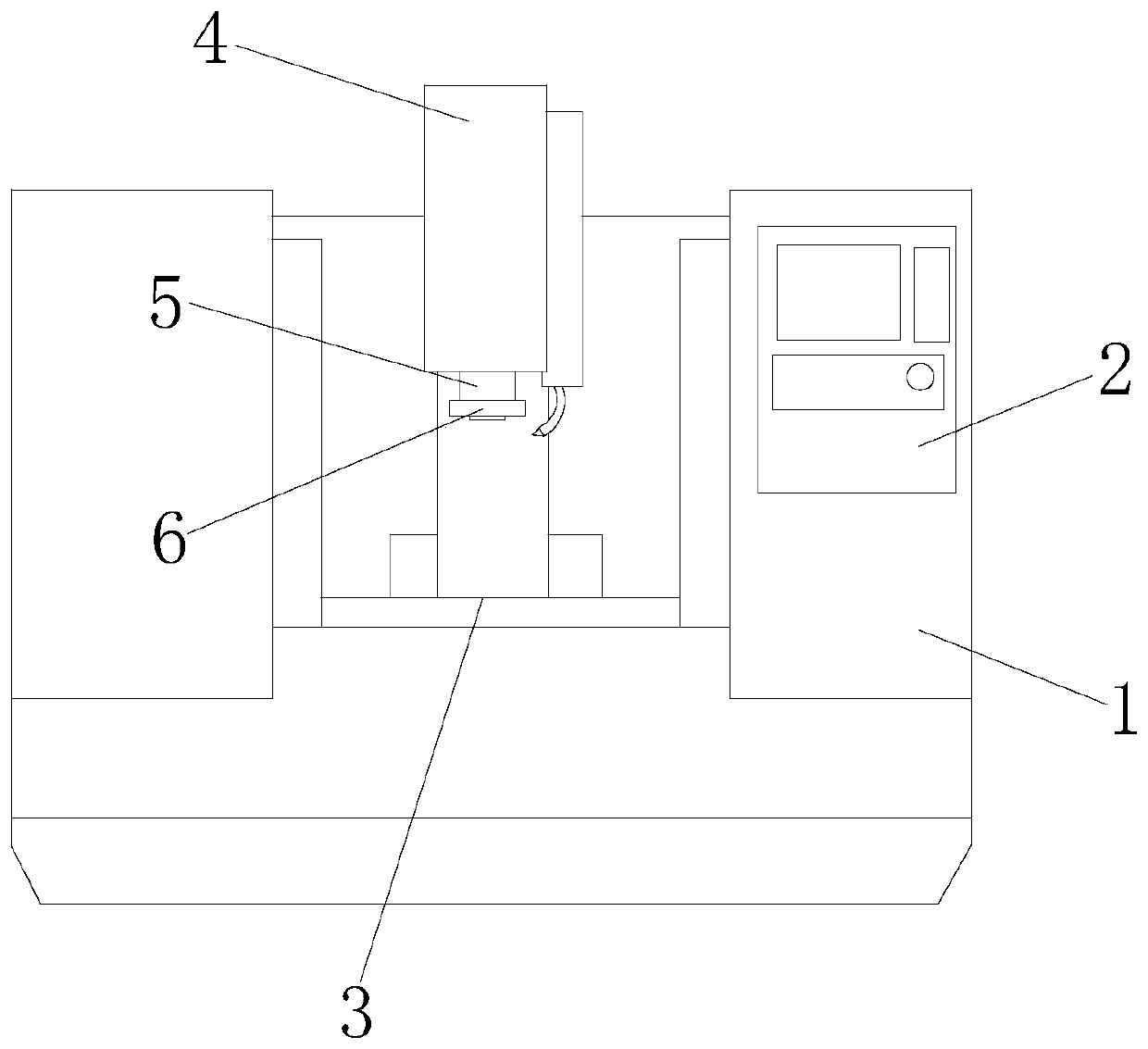
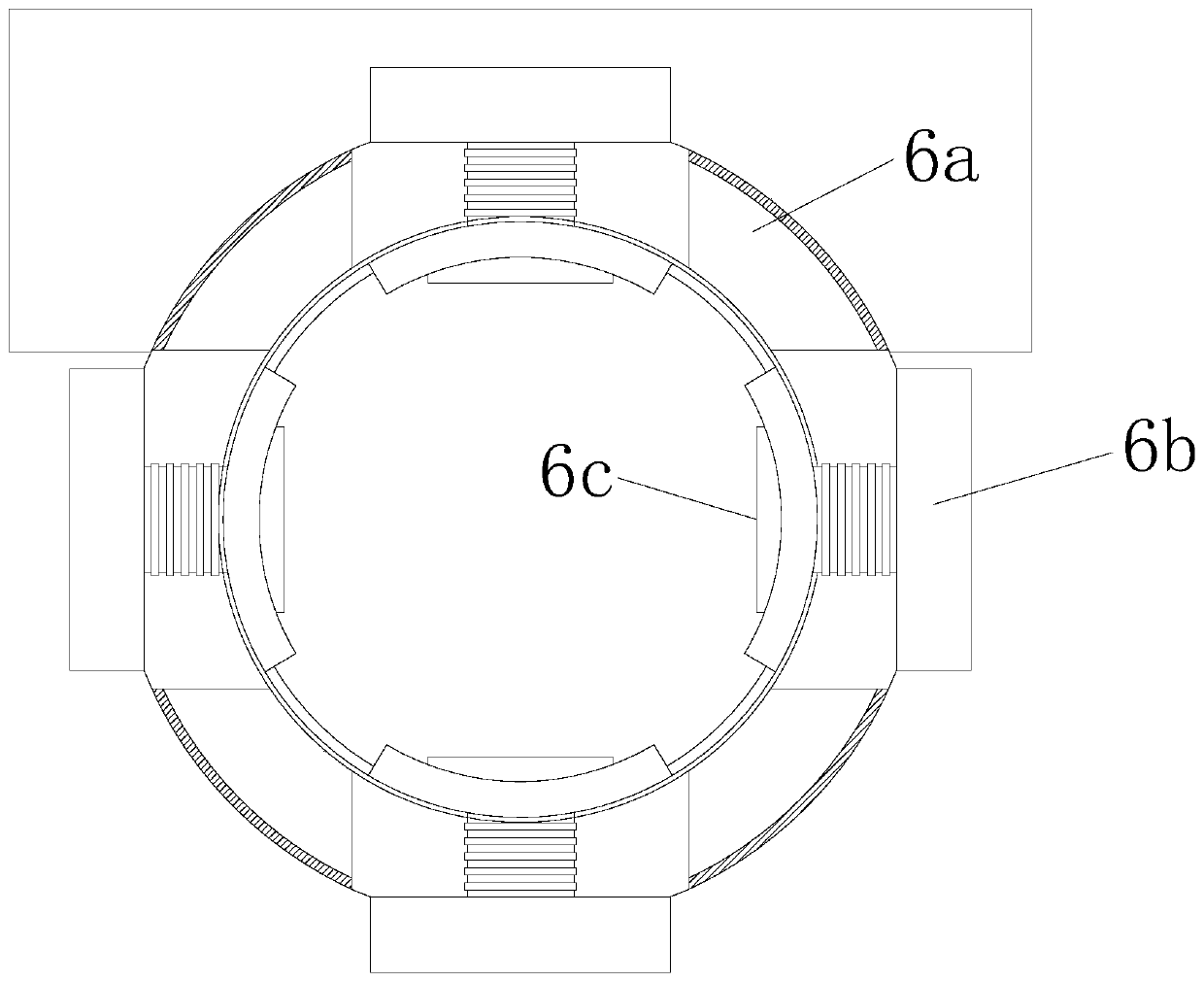
[0030] Such as Figure 1-Figure 2 As shown, a numerically controlled metal cutting machine tool, its structure includes a main body 1, a controller 2, a workbench 3, a column 4, a machine head 5, and a cleaning device 6, and the controller 2 is installed on the right side of the front surface of the main body 1. side and connected by electric welding, the workbench 3 is set on the upper part of the equipment main body 1 and is an integrated structure, the column 4 is set on the middle part of the front surface of the equipment main body 1 and is located directly above the workbench 3, the machine head 5 Installed on the lower surface of the column 4 and connected by electric welding, the dirt cleaning device 6 is installed on the outer surface of the machine head 5 and connected by buckling, the dirt cleaning device 6 includes...

no. 2 example

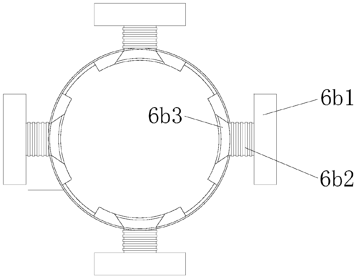
[0039] Such as figure 1 , figure 2 , Image 6 As shown, the present invention provides a technical scheme of a numerically controlled metal cutting machine tool:

[0040] Such as Figure 1-Figure 2As shown, a numerically controlled metal cutting machine tool, its structure includes a main body 1, a controller 2, a workbench 3, a column 4, a machine head 5, and a cleaning device 6, and the controller 2 is installed on the right side of the front surface of the main body 1. side and connected by electric welding, the workbench 3 is set on the upper part of the equipment main body 1 and is an integrated structure, the column 4 is set on the middle part of the front surface of the equipment main body 1 and is located directly above the workbench 3, the machine head 5 Installed on the lower surface of the column 4 and connected by electric welding, the dirt cleaning device 6 is installed on the outer surface of the machine head 5 and connected by buckling, the dirt cleaning de...


PUM


Abstract

The invention discloses a numerical control metal cutting machine tool. The numerical control metal cutting machine tool structurally comprises an equipment main body, a controller, a workbench, a stand column, a machine head and a scale cleaning device. The numerical control metal cutting machine tool has the beneficial effects that oil dirt left on the surface of the machine head due to long-term operation is further scraped through scale scraping mechanisms so as to prevent the situation that the machine head operates at a low speed due to thickened oil dirt and a rotating fault occurs to the machine head of equipment under the opposed impact action of high-speed operation; an antimagnetic structure is used for eliminating thermal magnetization generated from high-speed rotating to thesurface of the machine head and adsorbing metal scraps produced during operation; the antimagnetic structure is used for adsorption treatment on the metal scraps, so that data errors occurring in thecutting process due to excess metal scraps adhering to the machine head is avoided.

Description

technical field [0001] The invention relates to the field of machining of mechanical parts, more precisely, it is a numerically controlled metal cutting machine tool. Background technique [0002] In mechanical equipment, some small parts of bolts and shafts are particularly important in the component parts of the equipment, so when processing such parts, the accuracy of their dimensions is particularly important. But existing metal-cutting machine tools have the following defects when processing this type of metal: [0003] There are a lot of metal shavings on the surface of the cutting head. When the cutting head is running fast, it is prone to frictional heating, so it is easy to make a large amount of metal shavings collect on the surface, thus affecting the normal cutting work of metal. At the same time, due to the influence of the working environment, there will be a large amount of oil stains on the surface of the machine head, resulting in slow operation. Contents...

Claims


Application Information

Patent Timeline
IPC IPC(8): B23Q11/00
CPCB23Q11/0042B23Q11/0046
Inventor 王坤
Owner 江苏中智自动化股份有限公司
Why Eureka
Try Eureka