Automatic mold taking device for mold

An automatic and mold technology, applied in the field of automatic mold taking device, can solve the problems of labor consumption, increase production cost, low work efficiency, etc., and achieve the effect of reducing labor consumption, increasing work efficiency, and quickly collecting and processing

Active Publication Date: 2020-05-08
南京君平智造科技有限公司
View PDF7 Cites 1 Cited by
  • Summary
  • Abstract
  • Description
  • Claims
  • Application Information

AI Technical Summary

Problems solved by technology

[0005] In order to overcome the shortcomings of the current mold removal method that consumes manpower, the work efficiency is not high, and the production cost is increased, the purpose of the present invention is to provide a mold that can automatically remove the mold, reduce the production cost, and improve production efficiency. Automatic mold taking device

Method used


Image

  • Automatic mold taking device for mold
  • Automatic mold taking device for mold
  • Automatic mold taking device for mold

Examples


Embodiment 1

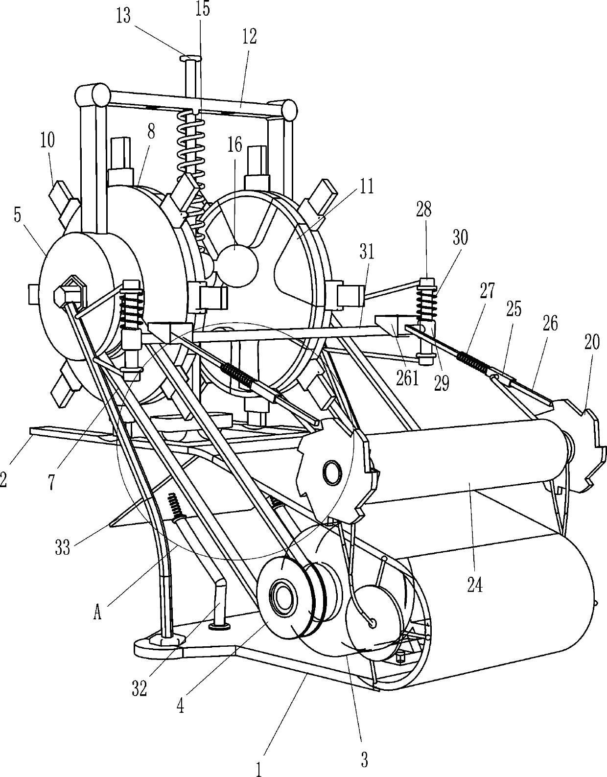
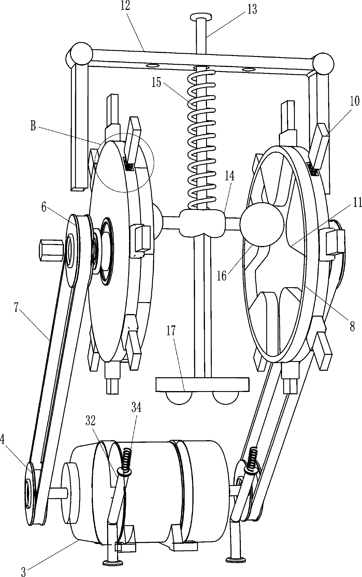
[0020] A kind of mold automatic mold taking device, such as figure 1 , 2 As shown in and 5, it includes a tray 1, a loading plate 2, a double-axis reduction motor 3, a transmission assembly and a mold taking assembly. The top of the tray 1 is provided with a loading plate 2, and the top of the tray 1 is provided with a double-axis reduction motor 3. The double-axis deceleration motor 3 is located between the tray 1 and the loading plate 2, and the left side of the top of the tray 1 is provided with a transmission assembly powered by the motor, and a mold-taking assembly for taking the mold by knocking is provided between the transmission assemblies. The transmission assembly cooperates with the mold taking assembly.

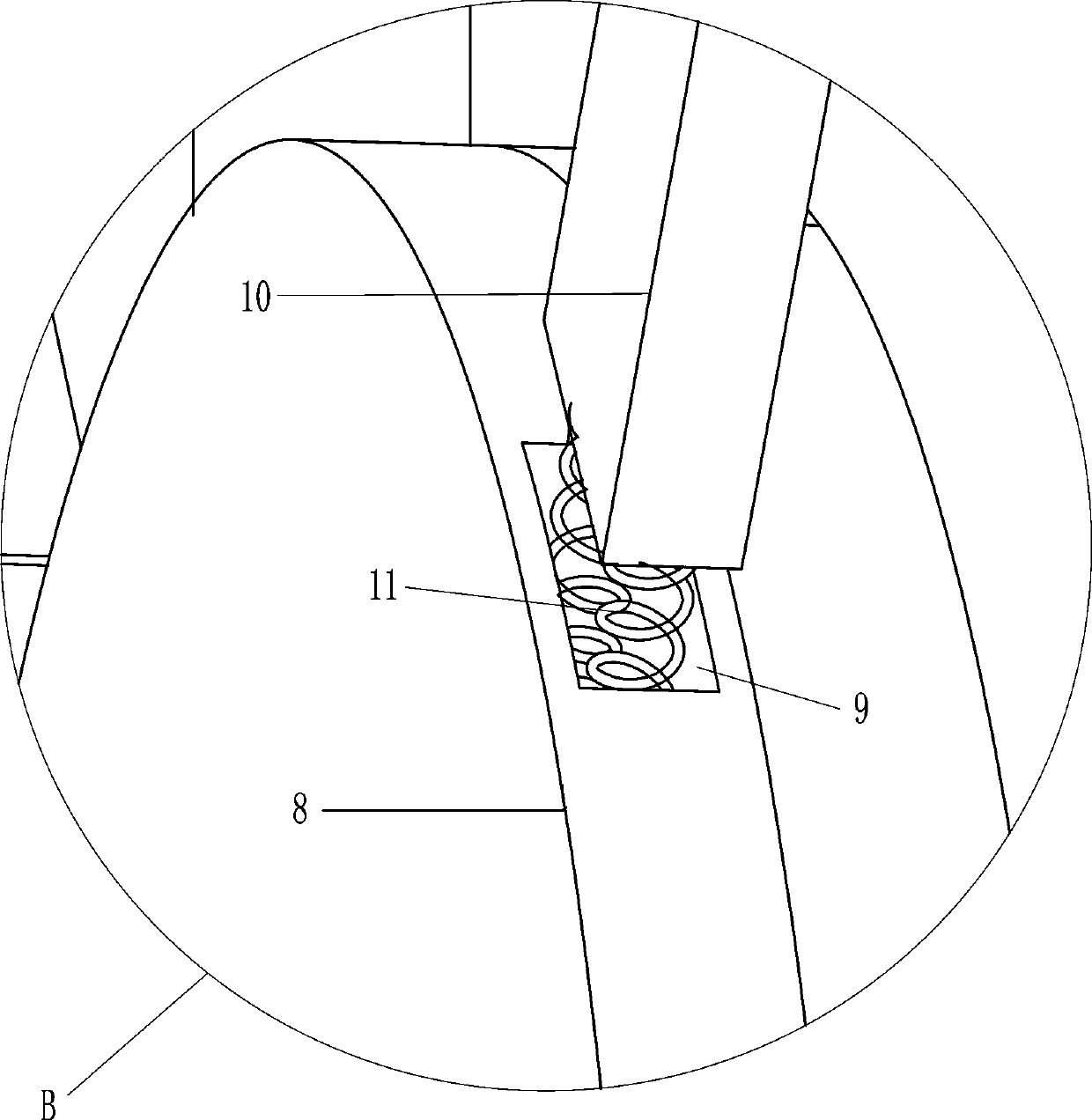
[0021] Such as figure 1 , 2 As shown in and 5, the transmission assembly includes a first pulley 4, an installation housing 5, a second pulley 6, a flat belt 7, a turntable 8, a slider 10 and a first spring 11, and the output shaft of the biaxial reduction mot...

Embodiment 2

[0027] On the basis of Example 1, such as figure 1 , 3 As shown in and 4, in order to improve the practicability of the equipment, it also includes a rotating shaft 18, a second mounting block 19, a ratchet 20, a star block 21, a third spring 22, a roller 24, a guide sleeve 25, and a second slide bar 26. Wedge block 261, fourth spring 27, guide rod 28, sliding sleeve 29, fifth spring 30 and cross bar 31, the front and rear parts of the top right side of the tray 1 are welded with the second mounting block 19, the second mounting block 19 The inner uniform rotation type is provided with a rotating shaft 18, the inner side of the rotating shaft 18 is provided with a star-shaped block 21, the outer end of the rotating shaft 18 is provided with a ratchet 20, and a third spring 22 is arranged between the star-shaped block 21 and the second mounting block 19. The three springs 22 are in contact with the second mounting block 19, and a roller 24 is arranged between the rotating shaf...


PUM


Abstract

The invention relates to a mold taking device, in particular to an automatic mold taking device for a mold. According to the automatic mold taking device for the mold, the mold can be automatically taken down, the manufacturing cost can be reduced, and the the production efficiency can be improved. The automatic mold taking device for the mold comprises a tray, a carrying plate, a double-shaft gear motor, a transmission assembly, a mold taking assembly and the like; and the carrying plate is arranged at the top of the tray, the double-shaft gear motor is arranged at the top of the tray, the double-shaft gear motor is located between the tray and the carrying plate, and the transmission assembly powered by the motor is arranged on the left side of the top of the tray. According to the automatic mold taking device for the mold, by means of the transmission assembly and the mold taking assembly, the mold can automatically move rightwards, meanwhile, in the rightward moving process of themold, mold taking can be automatically carried out, after mold taking of the mold is completed, the remaining mold plates can be wound and collected, and therefore the mold plates can be rapidly collected and treated.

Description

technical field [0001] The invention relates to a mold taking device, in particular to an automatic mold taking device. Background technique [0002] Mold refers to various molds and tools used in industrial production for injection molding, blow molding, extrusion, die-casting or forging forming, smelting, stamping and other methods to obtain the required products. In short, molds are tools used to shape objects It mainly realizes the processing of the shape of the article through the change of the physical state of the formed material. It is widely used in blanking, die forging, cold heading, extrusion, powder metallurgy parts pressing, pressure casting, and engineering plastics, rubber, ceramics and other products. In the forming process of compression molding or injection molding; after the mold forms the product, it is necessary to take the mold of the product, so people need to knock the mold on the carrier plate. [0003] At present, when removing the mold on the loa...

Claims


Application Information

Patent Timeline
Patent Type & Authority Applications(China)
IPC IPC(8): B29C33/44
CPCB29C33/44
Inventor 陈炳华
Owner 南京君平智造科技有限公司
Why Eureka
Try Eureka